This thread has been locked.

If you have a related question, please click the "Ask a related question" button in the top right corner. The newly created question will be automatically linked to this question.

TIDM-02009: Purpose of current transformer at HV input

Part Number: TIDM-02009
Other Parts Discussed in Thread: TIDM-02000

Hi, I'm investigating the schematic of TIDM-02009.

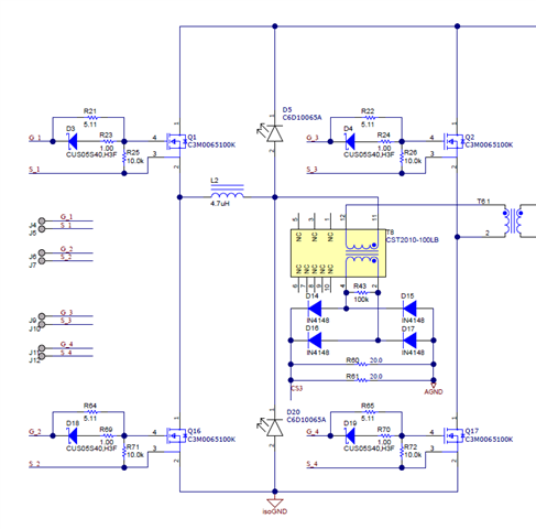
1) What is the purpose of current transformer at below figure? Is it for protection or current mode control or boost mode current measurement?


2) What is the purpose of putting current transformer (T8) in between transformer and clamping diodes (position perspective)? It might be placed in series with L2. It is used for PCMC operation but its inductance cannot be clamped through diodes.
3) Is current transformer at that location required for also boost mode of operation? Is it also required for boost operation? (Below figure)

  • Hi Gokhan, same as the previous response, let me double check it the h/w designer before I get back to you with the details. 

  • Hi Gokhan, pls have the response below for your questions 1) ~ 3):

    Question 1):  the purpose of current transformer is for PCMC current sensing and control, and the protection function is included. The boost mood is supported by the h/w design, but the corresponding s/w is not part of the solution yet.

    Question 2) & 3): The circuit is reserved for other/coming feature consideration and is a redundancy in this design.

  • Hi Hui,

    1) I thought that T8 is used for PCMC, because it is in series with transformer and flux balance is achieved by this way. Could you please correct again?

    2) Could you please write me the ADC ports and name of signals corresponding to CS3 and Ipri? I wil follow the code in this way.

    (Ipri is generated by CT1 and CT2.)

  • Gokhan,

    1) The T1 is giving a rectified version of the inductor current, which will make PCMC implementation easier. For details on how we use CMPSS on C2000 to implement PCMC on PSFB, please refer to design guide of TIDM-02000.

    2) The PCMC is implemented with CMPSS, not via ADC reading.

    Han

  • Han, Thank you for clear answer.

    1) The T1 is giving a rectified version of the inductor current, which will make PCMC implementation easier. For details on how we use CMPSS on C2000 to implement PCMC on PSFB, please refer to design guide of TIDM-02000.

    Q1.1) Yes, T1 gives a rectified version of primary transformer current and which also means that output inductor current. However, T8 also can handle same issue. It is close to transformer and can perform better performance also fixing mismatch at power switches. So, which benefits exists using T1 instead of T8?

    Q1.2) TIDM-02000 has also Cb capacitor optional, if PCMC achieves flux balancing why do I still need Cb?

    2) The PCMC is implemented with CMPSS, not via ADC reading.

    Q2) Yes, but it is connected to ADC port and its bypassed inside the module and internal comparator used. I need to follow software but I cannot follow it because I cannnot follow signal name.  Could you please write me the ADC ports and name of signals corresponding to CS3 and Ipri? I wil follow the code in this way.(Ipri is generated by CT1 and CT2.)

    2) What is the purpose of putting current transformer (T8) in between transformer and clamping diodes (position perspective)? It might be placed in series with L2. It is used for PCMC operation but its inductance cannot be clamped through diodes.
    3) Is current transformer at that location required for also boost mode of operation? Is it also required for boost operation? (Below figure)

    I also repeat my question in those manners. If answer is same, it is OK.

  • Hi Gokhan,

    Thanks for following up. Please see my comments below.

    Q1.1) Sure you can also use T8 for it, we just made the design choice at the time.

    Q1.2) No, you do not need Cb, and it is bypassed during testing of PCMC. It is only required if you do average current mode control.

    Q2) Sure, the Ipri signal is connected to HSEC pin 25 --> MCU ball T4 --> ADCIN14 and CMPIN4P. Thanks.

    2) Since we did not plan to use T8 for PCMC, we did not thought about that along this line. If you want to use a CT in series of inductor for PCMC, you can place it on the left of diodes.

    3) For boost mode operation, it is only intended for pre-charging some line capacitor, not for high power or long period operation. We does not have software support for this mode on TIDM-02009 on public released version at this time. You can refer to TIDM-02000 for reference on reverse mode operation with center-tap secondary. If you need further support on reverse operation, please contact your local TI field support team to request support. Thanks.

    Han

  • Hi Han,

    Thank you for your help.