Other Parts Discussed in Thread: C2000WARE, , SYSCONFIG
Tool/software: Code Composer Studio
dear yanming,
Build Level 2 & 3:
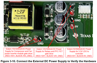
We have set these parameter as per specification:
#if (USER_MOTOR1 == Voepl_ODU_compressor_motor) //added by Babaji Nemnar 18032023
#define USER_MOTOR1_TYPE MOTOR_TYPE_PM
#define USER_MOTOR1_NUM_POLE_PAIRS (3)
#define USER_MOTOR1_Rr_Ohm (0.0)
#define USER_MOTOR1_Rs_Ohm (0.838)
#define USER_MOTOR1_Ls_d_H (0.0085737)
#define USER_MOTOR1_Ls_q_H (0.01210875)
#define USER_MOTOR1_RATED_FLUX_VpHz (0.377903223) Note: this parameter is not present in the specification,Please guide how to set.
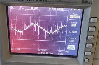
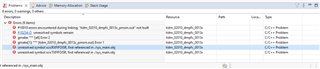
After Run the Code:
Copressor worked for 2 second & stop.Refer attachment expression window with queries.
Please guide.