This thread has been locked.

If you have a related question, please click the "Ask a related question" button in the top right corner. The newly created question will be automatically linked to this question.

TMS320F280049C-Q1: Recommend a suitable external op-amp to replace internal PGA

Part Number: TMS320F280049C-Q1
Other Parts Discussed in Thread: TMS320F280049C, TMS320F280039C

Dear TI expert,

    At my project, TI C2000 TMS320F280049C is used to control the digital power supply.

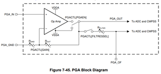
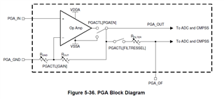
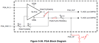
    The output voltage will feedback into C2000 internal PGA through resistor divider, then go to the ADC, then to do dynamic control. If needed, to adjust the PWM duty to the digital power supply.

    Currently TI TMS320F280049C is in shortage, thus you suggest us to use TMS320F280039C. However, inside TMS320F280039C, there is no PGA available, then it means we need to find a external op-amp as instead.

    So do you have any suggested op-amp for us to replace the PGA inside TMS320F280049C? 

    Besides, we are also trying to find suitable op-amps by ourselves, however, we have some doubt regarding to some parameters of the PGA inside TMS320F280039C? Could you help give us your explanation?

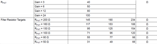
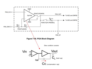
    1. Why slew rate is changing with gain change? as per my knowhow, slew rate should be somehow a fixed value.


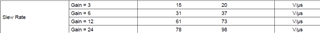
    2. Why the bandwidth is same for all gain setting(3,6,12,24)? Also, as per my understanding, the gain bandwidth product should be somehow a fixed value.


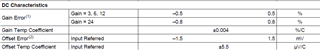
    3. Below the gain error and offset error values is before your hardware trim or after your hardware trim?


    Thanks for your time on this in advance!

  • Hello,

    Thank you for your patience.

    1. The slew rate of the amplifier is determined by the rate at which the output stage can charge or discharge the parasitic capacitance at its output. As the gain of the PGA is increased, the feedback network introduces additional capacitance into the circuit, which can increase the overall capacitance seen by the output stage.
    2. I’m not sure where you got this information, but the bandwidth changes with gain (as shown in datasheet section 7.10.2.1.2 PGA Characteristics). In PGA, the gain of the amplifier is controlled by changing the value of the feedback resistor. When the gain is increased, the feedback resistor value decreases, which in turn decreases the feedback capacitance of the amplifier. This reduction in capacitance causes the bandwidth of amplifier to reduce.
    3. These errors values are after trim

    Regards,

    Hadi

  • Hi TI expert:

        Thanks for your feedback!

        1. You said when PGA gain increased, the feedback network will introduce additional capacitance, where does this additional capacitance come from? Based on below circuit in datasheet, I can't find it. Also as per my understanding, if capacitance is bigger, the slew rate will decrease, right?


        2. Previously I used Rev.E datasheet, but in your latest Rev.G datasheet, bandwidth parameter values are updated. Additional question from my side, when you test the bandwidth, do you connect any R load or C load to the PGA circuit?

        3. Got it, thanks for your info!

        Additionally, do you have any suggested op-amp for us to replace the internal PGA?

  • Hello Chang,

    1. Sorry for the mistake... As I explained in question 2, when the gain is increased, the feedback resistor value decreases, which in turn decreases the feedback capacitance of the amplifier. As you said, the slew rate increases if the capacitance decreases. For more information about the parasitic capacitance of op-amp, you can refer to the application report "Effect of Parasitic Capacitance in Op Amp Circuits".

    https://www.ti.com/lit/ml/sloa013a/sloa013a.pdf?ts=1679937077569&ref_url=https%253A%252F%252Fwww.google.com%252F

    2. For bandwidth, we use capacitor as a load.

    Also, for a replacement, you need to select an op-amp with the similar characteristics in terms of output common-mode, supply voltage, bandwidth, slew rate, noise, offset voltage drift, and CMRR.

    Regards,

    Hadi

  • Hi Hadi:

        Thanks for your feedback!

        1.  Sorry that I still don't understand this sentence "the feedback resistor value decreases, which in turn decreases the feedback capacitance of the amplifier", why feedback resistor has impact to feedback capacitance? Could you help explain more?

        2. I think when you test bandwidth, you used below circuit, could you tell me the RFILT resistor value and C load value during your test? By the way, during your test, the C load is connected to PGA_OF pin, right?


        The selectable RFILT value is as below.


        Besides, thanks for your suggestion for us to select the correct op-amp to replace the internal PGA.

  • Hi Chang,

    Let me talk to our design team to get the PGA internal circuit.

    I'll let you know.

    Thanks,

    Hadi

  • Hello Chang,

    Thank you for your patience.

    1) Following you can see the internal circuit of PGA. As you can see, 2 stage op-amps need compensation cap for stability and bandwidth improvement. Ideally both CL and Cc determine slew rate. But, Cc is dominant effect. 

    2) The capacitor value is 1nF and the RFILT values should be selected based on the gain.

    For op-amp selection, you can go to TI.COM and select op-amp based on the required supply voltage, bandwidth, slew rate, noise, offset voltage drift, and CMRR.

    Regards,

    Hadi

  • Hi Hadi:

        Thanks for your feedback!

        1. I think your explanation doesn't explain "why feedback resistor has impact to feedback capacitance", could you double check this?

        2. So the test circuit for bandwidth parameter in your datasheet is as below, right?


  • Hi Chang,

    1) As the feedback resistor value decreases, the required compensation capacitance decreases ; so, it turns in increases the slew rate.

    2) 


    Regards,

    Hadi

  • Hi Hadi:

        Thanks for your info!

        Currently the answer is clear to me now, really appreciate your support!