Other Parts Discussed in Thread: TMDSCNCD28379D
Hello,
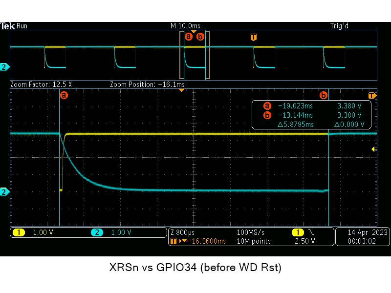
I am working on setting up the WD and I noticed the reset time value using a scope plugged on the XRSn pin is not what I expected.
After enabling the WD with a presale of 1 (WDPS = 0, WDCLK = INTOSC1/512/1), I am expecting to have a time between each continuous WD reset around 13.1ms with INTOSC1 = 10 MHz.
1/(10MHz/512) * 256 (WDCR) = 13.1ms.
I measure around 19ms (see below):
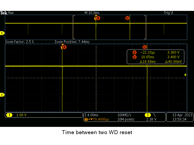
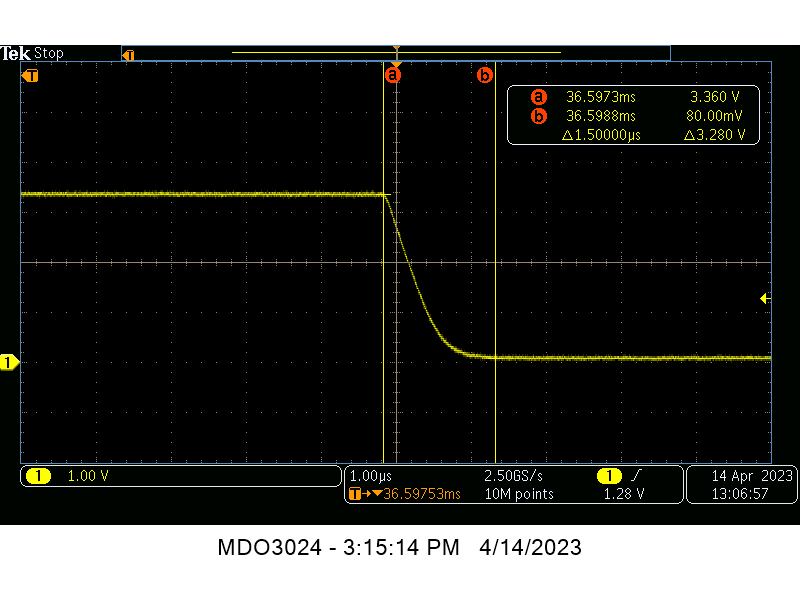
Then, when I measure the time of the XRSn, I am expecting to get 512 x INTOSC1 = 51.2us (per the datasheet) but I measure around 60us (see below):
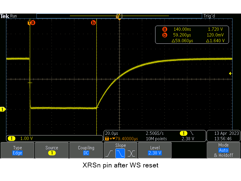
Does anyone know what is going on?
Thank you.
Laurent