Hi,
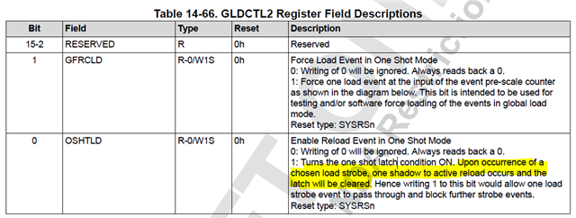
Problem Statement: Overlap occurs between PWM 1A & 3B or 1B & 3A at randomly as shown in waveform below.
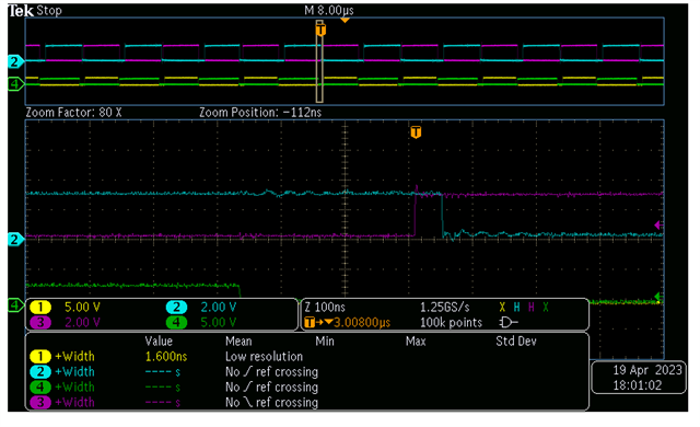
Yellow:- PWM1A, Blue: PWM1B, Pink: PWM3A, Green:- PWM3B
Configuration details
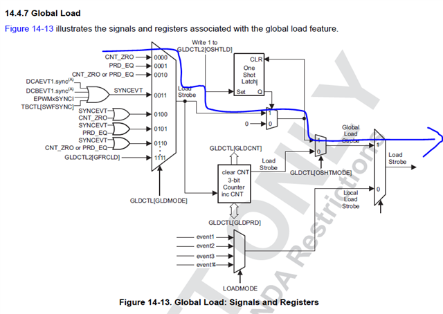
-> We are using One shot load mode for PWM duty & dead band register update at PWM counter = 0.
-> Here PWM 1 & PWM 3 counters are in sync however PWM 1 is used for Primary pulses and PWM3 is used for Sync rectification. Normal waveform are as shown below.
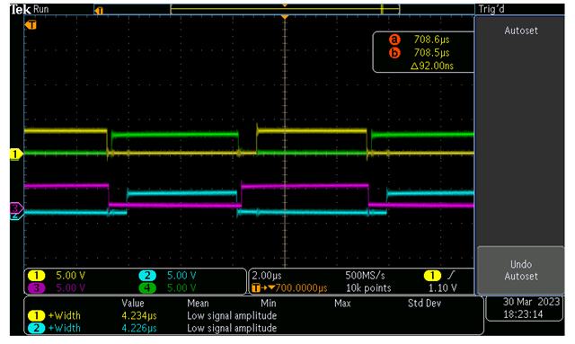
Yellow:- PWM1A, Blue: PWM1B, Pink: PWM3A, Green:- PWM3B
-> On PWM1 & PWM3 dead band module is activated and updated at every cycle based on control loop requirement.
-> The control loop execution is asynchronous to PWM counter.
-> Hence although loading event is known, loading status is unknown.
-> Is there any provision to understand if the One Shot load is executed, so that next PWM shadow register update can be only executed if checking the status.
-> e.g. if Clear bit status is known in OSTLATCH, execution status can be known.