This thread has been locked.

If you have a related question, please click the "Ask a related question" button in the top right corner. The newly created question will be automatically linked to this question.

TMS320F280025: Overvoltage during flying start

Part Number: TMS320F280025
Other Parts Discussed in Thread: TIDM-02010, MOTORWARE

Dear support team.

I'm working with my own motor and DRV8353RS, 3 shunt and TMS320F280025 lanch pad.

The motor is runing fine I just have a small issue during flying start.

I use universal motor control lab from SDK 4_02_01_00.

As discussed before, those parameters as been set:

    obj->flagEnableFlyingStart = true; 

obj->flyingStartTimeDelay = (uint16_t)(objUser->ctrlFreq_Hz * 0.5f); // 0.5s

#define USER_MOTOR1_SPEED_FS_Hz            (3.0f)

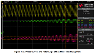
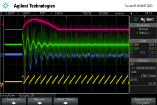
During flying start I have an overvoltage (about 10V for 28V power supply), see below:
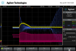
Yellow : DC voltage

Blue : current in the motor (10mV=500mA)

Pink : MOT B voltage

As you can see, when the flag motorVars_M1.flagEnableRunAndIdentify is set to 1, the current take a few ms before regulating to 0 and during this time, there is an overshoot on the DC voltage

Then after 0.5s, the motor accelerate as expected.

The offset calculation is not enabled.

I have in mind something like if the current regulator setpoint is not correctly set.

I try to increase the flying start delay but it just delay the time when the motor accelerate, the overshoot is the same.

Can you help me to reduce this overvoltage?

With best regards

  • Hi,

    Is your motor spinning before re-starting with flying start enabled, and in the desired direction (matching USER_MOTOR1_SPEED_FS_Hz)? Can you try plotting the rotor angle to see if it's detecting the angle / speed properly before it starts to output to the motor. Can plot using external DAC or in CCS graph tool.

    See below from TIDM-02010 document for reference:

    Figure 3-32 is a screen shot when the fan motor is running with the flying start feature. It shows
    CH1 (Yellow): Rotor angle output by a DAC
    CH2 (Green): Sensing phase current output by a DAC
    CH4 (Pink): Measured phase current with a current probe

    Best,

    Kevin

  • Hi, 

    Is your motor spinning before re-starting with flying start enabled, and in the desired direction (matching USER_MOTOR1_SPEED_FS_Hz)?

    Yes motor is spinning in the desired direction.

    Can you try plotting the rotor angle to see if it's detecting the angle / speed properly before it starts to output to the motor. Can plot using external DAC or in CCS graph tool.

    See below the measurment:

    Pink : Dc voltage

    Green : Dac CH_B = adcData.I_A.value[0]

    Blue : current in the motor

    Yellow : Dac CH_A = angleFOC_rad

    The graph you share is not at the same time than mine, the graph you share is when motor current increase to drive the load so after the flying start delay. After the flying start delay, I don't have any overvoltage.

    Regards.

  • What observer algorithm are you using? FAST? eSMO? Currently, the flying start is only working with FAST estimator.

  • Yes, FAST is used.

    For information, I have simiilar issue in the past with the old motorware and old evaluation kit (flying start was not a standard behaviour of the motorware at this time).

    see below:

    https://e2e.ti.com/support/microcontrollers/c2000-microcontrollers-group/c2000/f/c2000-microcontrollers-forum/327771/flying-start-overvoltage

    The reasons were:

    -the driver which was used on the evaluation kit need several ms to initialise => this was solved with my own hardware.

    -it was necessary to seed both current controllers to the backEMF of the motor before enabling current controllers

    Now that flying start is part of the motor control SDK, I assume that there is no need to add this but perhaps I'm wrong.

    Regards.

  • -it was necessary to seed both current controllers to the backEMF of the motor before enabling current controllers

    It's optional that depends on the hardware. Seems like the FAST estimator doesn't work before you start to run the motor. The right waveform should be similar as the picture Kevin posted above. The FAST estimator was enabled always to detect the rotor angle and speed before spin the motor with speed closed-loop.

    Did you make any changes in the example project? Or just enabled the Flying Start by setting the flag as you mentioned above?

  • The right waveform should be similar as the picture Kevin posted above

    I didn't agrre with this, as I said, the waveform posted by kevin is not at the same time:

    In the standard universal motor control lab, there is a 0.5s timeout. During this timeout, Id and Iq are set to 0 and at the end of the timeout, Id and Iq are set to normal values.

    We can see in Kevin waveform that current start to increase, so it means that begining of the timeout is out of the screen (on the left side).

    The overvoltage and my waveform are at the begining of the timeout, just when PWM are enabled. At the end of the timeout, I don't have any issues.

    For information, I try to delay a few ms PWM enabling but the result was similar.

    I made some small changes but it should'nt have such impact. I will verify or going back to original motor control lab.

    Regards.

  • For information, I made additionnal tests:

    -back to original motor control lab SDK 4_02_01_00 (without any changes other that motor parameters and enabling flying start) : overvoltage is the same

    -back to an old project with SDK 4_00_00_00 : overvoltage is lower (divided by 3).

    So I focus on  Kp/Ki, especially for Id and Iq current which are different from 4_00_00 and 4_02_01 : so with the same Kp, I reduce the overvoltage also for 4_02_01.

    By increasing again, the overvoltage is reduced again.

    The peak current is not reduced a lot but it goes down to zero quicker which help regarding the overvoltage.

    For sure the result is better but it will be preferable not to have peak current because on the final project, voltage and capacitor will be different so perhaps the impact will be higher.

    Regards.

  • The major issue is that the FAST estimator didn't work before the motor start. The issue is just at the first time start motor after the board is powered on, or at any time to start the motor?

  • This is at any time.

    For information I made the following measurment:

    -I add a RC filter at the motor phase so that I can see the mean value of the PWM switching voltage. I can clearly see that when PWM is enabled, the voltage between motor phase didn't follow the back EMF for a short time and this create the first and higher current peak.

    So for me current controller need to be aligned with back-emf.

  • Hi Manu36,

    Curious have you try to change any PWM settings (hal.c) as period shadow loads CMPA on versus forced loads? Wonder if EMF keeps better sync with PWM drive via PARK from below settings. Obviously, estimator is running in your capture as the angle is present but the PWM is MIA and it looks like inductive kick back occurs. The commented sync on software call was not found in x49c driverlb and passed compiler warning. The sync out pulse on zero will keep two slaves via master in sync with CMPA match up. It's worth a try to see if it helps at all to shorten or arrest the electrical disturbance.

    //EPWM_setPeriodLoadMode(obj->pwmHandle[cnt], EPWM_PERIOD_DIRECT_LOAD);

    // set the period load mode quiet shadow loading
    EPWM_setPeriodLoadMode(obj->pwmHandle[cnt], EPWM_PERIOD_SHADOW_LOAD);

    EPWM_setSyncOutPulseMode(obj->pwmHandle[cnt], EPWM_SYNC_OUT_PULSE_ON_COUNTER_ZERO);

    //EPWM_enableSyncOutPulseSource(obj->pwmHandle[cnt], EPWM_SYNC_OUT_PULSE_ON_SOFTWARE);

  • -I add a RC filter at the motor phase so that I can see the mean value of the PWM switching voltage

    What do you mean this?  You add a RC filter on the output of the inverter to the motor lines? What RC filter?

  • have you try to change any PWM settings (hal.c) as period shadow loads CMPA on versus forced loads

    No.

    I have try the suggested changes( EPWM_setSyncOutPulseMode(obj->pwmHandle[cnt], EPWM_SYNC_OUT_PULSE_ON_COUNTER_ZERO); was replaced by EPWM_enableSyncOutPulseSource(obj->pwmHandle[cnt],EPWM_SYNC_OUT_PULSE_ON_CNTR_ZERO); due to error).

    There is no visible difference.

  • The RC filter is just in parallel to filter the PWM frequency for scope measurment. I just add it for the last test, it was not connected before. I don't remember the value of R and C I made it a long time ago but the resistor is hight to prvent a difference in the current that can disturb FOC.

  • I have try the suggested changes

    What about direct loading PWM function? Something seems to clamp (lock) or disable PWM output during the 500ms delay. Seemingly flying start should set 50% duty-cycle (zero current) so the inverter does not enter regeneration for 500ms. Assuming the scope capture indicates a voltage spike occurs when PWM is not present. Does the volage spike trip a OVC fault?

  • Something seems to clamp (lock) or disable PWM output during the 500ms delay

    I did'nt agrre with this:

    -see pink waveform in the first post, we can see the PWM switching frequency and also current waveform will be different if it was the case (curent converge to zero due to Iq/Id regulator, not due to a speed change of the motor which is already spining). And also I clearly saw that changing Iq/Id regulator decrease the overvoltage if regulator are more reactives.

    Seemingly flying start should set 50% duty-cycle (zero current) so the inverter does not enter regeneration for 500ms

    The regeneration is not during 500ms but only 50ms, when Iq and Id regulator stabilise the current to 0, there is no more regeneration.

    I did not agree with the 50% duty cycle. If motor is spinning, it will create voltage different to 50% duty cycle and it will create current flowing. The Duty cycle shoudl be set to the corresponding BEMF for each phase before PWM is enabled.

    This is why i said: 

    For information, I have simiilar issue in the past with the old motorware and old evaluation kit (flying start was not a standard behaviour of the motorware at this time).

    see below:

    https://e2e.ti.com/support/microcontrollers/c2000-microcontrollers-group/c2000/f/c2000-microcontrollers-forum/327771/flying-start-overvoltage

    The reasons were:

    -the driver which was used on the evaluation kit need several ms to initialise => this was solved with my own hardware.

    -it was necessary to seed both current controllers to the backEMF of the motor before enabling current controllers

    Regards.

  • The regeneration is not during 500ms but only 50ms, when Iq and Id regulator stabilise the current to 0, there is no more regeneration.

    Ok I see the PWM is driving phases but is somehow causing a rise of inductive current in 50ms time. I just recalled reading 500ms delay, not aware of 50ms time was capture as scope LCD show Delta X 1.3 seconds. Seeding the current controllers seems an odd way to slow current rise. Again if it does not trip an OVC fault is it not so bad an issue.

    Perhaps better to decelerate motor under PWM control, remove 500ms delay flying start. The decelerate code snip works great SDK 4.01, not yet tested with flying start though it resumes up to set trajectory speed without issues. 

                // Just increase or decrease the trajectory speed
                else
                {
                    TRAJ_setMaxDelta(trajHandle_spd,
                              (motorVars.accelerationStart_Hzps / USER_ISR_FREQ_Hz));
                }     
         
    /***********************************************************************************/
    
                /* Should motor decelerate or regenrate */
                if(bMainDecel)
                {
                    /* reduce acceleration, slowly decelerate to a stop */
                    motorVars.speedRef_Hz = USER_FORCE_ANGLE_FREQ_Hz; //USER_MOTOR_FREQ_LOW_HZ
    
                    /* Disable PWM drive anywhere near low hertz speed */
                    if(motorVars.speed_Hz <= USER_FORCE_ANGLE_FREQ_Hz)
                    {
                        /* Set EPWM A/B outputs disabled
                        * high impedance regeneration */
                        HAL_disablePWM(halHandle);
                        /* set user throttle pedal trajectory speed */
                        motorVars.speedRef_Hz = USER_MOTOR_SPEED_REF_HZ;
                        // update the reference to the trajectory of speed
                        //TRAJ_setTargetValue(trajHandle_spd, motorVars.speedRef_Hz);
                        /* Set motor offline not running */
                        motorVars.flagRunIdentAndOnLine = false;
                        /* leave controller enabled */
                        motorVars.flagEnableSys = true;
                        /* Clear the stop flag */
                        bMainDecel = false;
                        /* Update HID motor stopped */
                        bMainStop = true;
                    }
                }
     

  • I'm not sure to understand, you want to try to have a controlled deceleration instead of a real flying start?

    If true it is not possible for my application. Flying start is a requirment (but as I saw that the slower is the motor at flying start, the lower is the overvoltage, I have the possibility to allow the flying start at a speed which is ok for the overvoltage, if the speed is too high, I can wait for the speed to decrease).

    Actually no OVC is tripped but I dont' use the final board and final motor. Final board will be available in a few weeks but the maximum voltage (especially for capacitor) will be close to nominal voltage (for cost and size). So only a low overvoltage will be acceptable (10% to 20%).

    Seeding the current controllers seems an odd way to slow current rise

    I'm not sure, when PWM is enabled, if the generated voltage by PWM is different in phase and amplitude to the motor voltage, it will always create a curent, positive or negative according to the higher voltage. The current controller will change the PWM to converge to zero but it will always take time to react. 

    To be honest, this is not my idea, different TI experts discuss this in the forum (with me in the past or with other people).

    Sensored solution we develop internally set the SVM at the correct point before enabling PWM and there is no current flowing...

    Regards.

  • I'm not sure to understand, you want to try to have a controlled deceleration instead of a real flying start?

    Seemingly FOC decelerate under PWM control then assert flying start command at some point (no delay) or just decelerate and resume to a new set trajectory speed by throttle position or other means. Now use start button on LCD screen to resume during decelerate, not flying start and no OVTH issues.

    The SDK can assert SPI coast command for DRVIC but the half bridge has no idea what that is. MCSDK has brake commands the SDK did not have though it may have more aggressive attack rate than a simple decelerate, with trajectory tick counts to match a set attack rate. That was my next SDK experiment but MCSDK seems to have a default and faster attack rate in forever loop and ISR 25µs decimation at 20KHz.

  • The RC filter is just in parallel to filter the PWM frequency for scope measurment.

    You can not add any RC filter on the motor lines that will make the FAST estimator doesn't work well.

    How do you stop and start the motor? By changing the "motorVars_M1.flagEnableRunAndIdentify" in CCS debug expressions window?

    Can you post the motor parameters you used in the user_mtr1.h?

  • How do you stop and start the motor? By changing the "motorVars_M1.flagEnableRunAndIdentify" in CCS debug expressions window?

    Yes

    Can you post the motor parameters you used in the user_mtr1.h?

    #define USER_MOTOR1_TYPE MOTOR_TYPE_PM
    #define USER_MOTOR1_NUM_POLE_PAIRS (4)
    #define USER_MOTOR1_Rr_Ohm (NULL)
    #define USER_MOTOR1_Rs_Ohm (0.285154581)
    #define USER_MOTOR1_Ls_d_H (0.00202809973)
    #define USER_MOTOR1_Ls_q_H (0.00202809973)
    #define USER_MOTOR1_RATED_FLUX_VpHz (0.191983)
    #define USER_MOTOR1_MAGNETIZING_CURRENT_A (NULL)
    #define USER_MOTOR1_RES_EST_CURRENT_A (1.0f)
    #define USER_MOTOR1_IND_EST_CURRENT_A (-0.8f)
    #define USER_MOTOR1_MAX_CURRENT_A (6.0f)//au lieu de 3
    #define USER_MOTOR1_FLUX_EXC_FREQ_Hz (50.0f)
    #define USER_MOTOR1_OVER_CURRENT_A (9.0f) // A au lieu 6.5
    #define USER_MOTOR1_RATED_VOLTAGE_V (24.0f)

  • I will check and test the flying start function on the example lab and give you the feedback asap. What's the application? 

  • It is a fan application.

    Thank you for the support (it is really appreciated and it was part of the reasons we choose TI against competitors solutions).

  • Tested on a high voltage fan with High Voltage Kit since we don't have a low voltage fan. The flying start works well on this fan. Let me try to find why the estimator doesn't continue to work when you stop the motor. The flying start will enable the FAST estimator always to detect the rotor angle and speed if the flying start is enabled.

  • Let me try to find why the estimator doesn't continue to work when you stop the motor. The flying start will enable the FAST estimator always to detect the rotor angle and speed if the flying start is enabled.

    Any news about this?

    With best regards.

  • Seems like the flying start works well in the example lab. You may try to set a small value to "flyingStartTimeDelay" to reduce the voltage boost value.

  • Seems like the flying start works well in the example lab

    What does it mean?

    No overvoltage? No current peak? I can not imagine a different behaviour if the PWM is set to 50% when PWM are enabled. The impact can be different according to the speed of the motor at flying start, according to DC link capacitor value and according to other parameters.

    From an external point of view flying start also works if I did'nt look the voltage. If an overvoltage is created I will need to oversize my capacitor (value or voltage). Tha't why I try to reduce it.

    I still think that PWM duty cycle should be set according to the BEMF on each motor phase when PWM are enabled.

    Regards