This thread has been locked.

If you have a related question, please click the "Ask a related question" button in the top right corner. The newly created question will be automatically linked to this question.

TMS320F28379D: Double Band Hysteresis Modulation

Part Number: TMS320F28379D

Hi,

I'm implementing double hysteresis band modulation for my single phase inverter.

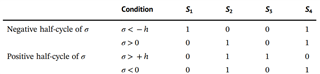
In the attached image σ is the sliding variable and h is the hysteresis band value.

I don't know how to configure EPWM module for this scheme, as i don't have any compare values directly.

Any help would be appreciated. Thank you.

NB: I have a restriction on my hardware that gate drivers are already connected through JTAG from controller. So, i cant use any of GPIO pins for gating signal.

  • Hi Binayak,

    Have you referred to the device TRM section 15.13 Applications to Power Topologies? If not, please take a look to see if any of those hint at what you are trying to achieve. 

    My familiarity is specific with configuring the EPWM module, so if you can help to explain or draw a diagram of the PWM output you are trying to create, that would be helpful for me to gain an understanding of what you are targeting and make suggestions on how to implement it Slight smile I will also check if we have any reference designs related to this that you can leverage.

    Best Regards,

    Allison

  • Hi Allison,

    Thanks for the reply.

    I have checked the TRM, unfortunately that's not what im looking for. I have attached an image in the original post.

    I have a sliding surface which is a linear combination of error states. This sliding surface is then compared with the hysteresis band to produce switching patterns given in attached image. Here i have double that, in EPWM module we have CMPA or CMPB registers with which we compare modulation values. Then according to AQ module we get the desired modulation. But in my case we are not using CMPA or CMPB. So, i don't know how to configure EPWM module.

    One more question is if i don't use EPWM module, i.e. directly using GPIO0 as output (not muxed as EPWM1A) can it introduce any delay? I have a sampling time of 0.2 us.

  • Hi Binayak,

    Thanks for the reply. We do have a single phase inverter reference design as well- please take a look here first and let me know if this helpful at all: 

    https://www.ti.com/tool/TIDM-HV-1PH-DCAC 

    Best Regards,

    Allison