Because of the Thanksgiving holiday in the U.S., TI E2E™ design support forum responses may be delayed from November 25 through December 2. Thank you for your patience.

TMS320F28377S: ADC is acquiring samples, how to see on oscilloscope ?

Part Number: TMS320F28377S

Tool/software:

Hi TI, 

I am trying to understand project implemented by someone else, which has

 ADC triggered with PWM1 and PWM5. with settings as below:

TBPRD= 1000 up and 1000 down = 2000

    EPWM_setCounterCompareValue(EPWM1_BASE,EPWM_COUNTER_COMPARE_C,20);// for ADC triggering
    EPWM_setCounterCompareShadowLoadMode(EPWM1_BASE,EPWM_COUNTER_COMPARE_C,EPWM_COMP_LOAD_ON_CNTR_ZERO);

    EPWM_setCounterCompareValue(EPWM5_BASE,EPWM_COUNTER_COMPARE_C,980);// for ADC triggering
    EPWM_setCounterCompareShadowLoadMode(EPWM5_BASE,EPWM_COUNTER_COMPARE_C,EPWM_COMP_LOAD_ON_CNTR_ZERO);
     
     
       EPWM_setADCTriggerSource(EPWM1_BASE,EPWM_SOC_A,EPWM_SOC_TBCTR_D_CMPC );
    // Generate pulse on 1st event
    EPWM_setADCTriggerEventPrescale(EPWM1_BASE,EPWM_SOC_A,1);
    // Enable SOC on A group
    EPWM_enableADCTrigger(EPWM1_BASE,EPWM_SOC_A);
   
    EPWM_setADCTriggerSource(EPWM5_BASE,EPWM_SOC_A,EPWM_SOC_TBCTR_U_CMPC );
    // Generate pulse on 1st event
    EPWM_setADCTriggerEventPrescale(EPWM5_BASE,EPWM_SOC_A,1);
    // Enable SOC on A group
    EPWM_enableADCTrigger(EPWM5_BASE,EPWM_SOC_A);

All ADCx modules have been used, with SOC starting from 0 - 13. 

ADC is triggered with SCO12 with settings as below . 

    Interrupt_register(INT_ADCC1, &ADC_ISR);
    ADC_setInterruptSource(ADCC_BASE ,ADC_INT_NUMBER1,ADC_SOC_NUMBER12);
    ADC_enableContinuousMode(ADCC_BASE ,ADC_INT_NUMBER1);
    ADC_enableInterrupt(ADCC_BASE,ADC_INT_NUMBER1);
    Interrupt_clearACKGroup(INTERRUPT_ACK_GROUP1);
    Interrupt_enable(INT_ADCC1);//GM adc oversampling
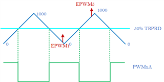
1. I understood this settings will acquire samples as shown in above fig., correct ? 

2. What flags i can use to toggle GPIO to see this sample acquisition on oscilloscope ?

3. I calculated total time taken by ADC module from SOC0 to SOC13 but how to confirm and measure it on oscilloscope ?

4. when ADC starts its conversion ? because i would like to toggle GPIO when SOC0 starts and trigger for SOC12 is generated using this flag ADCSOCFLG1

 I have  checked EPwm1Regs.ETFLG.bit.SOCA  to see if the SOC generated an event or not, working fine. 

I have checked AdccRegs.ADCINTFLG.bit.ADCINT1 to see if interrupt is generated or not, working fine. 

I appreciate any help i can get on this. 

  • Hi,

    I will have to get back to you towards the end of the week. I apologize for the delay. 

    Best Regards,

    Ben Collier

  • no problem, Awaiting your response. 

  • Hi Benjamin, 

    can i get your help on this ?

  • Hi,

    I apologize for the delay. 

    1. I understood this settings will acquire samples as shown in above fig., correct ? 

    Each ADC SOC can only be triggered by a single PWM. 

    2. What flags i can use to toggle GPIO to see this sample acquisition on oscilloscope ?

    I'm not sure what you mean by this, you can use any GPIO. 

    3. I calculated total time taken by ADC module from SOC0 to SOC13 but how to confirm and measure it on oscilloscope ?

    I think it would be easiest to output the PWM signal that triggers SOC0 and then measure a GPIO that has been toggled by and ISR that is triggered by SOC13.

    4. when ADC starts its conversion ? because i would like to toggle GPIO when SOC0 starts and trigger for SOC12 is generated using this flag ADCSOCFLG1

    I'm not sure I understand this question. Could you please clarify? 

    Best Regards,

    Ben Collier

  • I'm not sure what you mean by this, you can use any GPIO. 

    hi Benjamin, thank you for your reply. 

    Yes I can use any GPIO, but basically I wanted SET GPIO when SOC0 starts its conversion RESET GPIO when SOC12 conversion is triggered. I have set and clear GPIO45 in ADC ISR as seen in below code, but I am not getting expected time on oscilloscope when probed GPIO45. Could you help me understand why ?  ( I read in manual that says "1" in ADCSOCFLG1 indicates that sample is pending for that particular SOCx). 

        if( AdccRegs.ADCSOCFLG1.bit.SOC0 == 1)
        {
            GpioDataRegs.GPBSET.bit.GPIO45 = 1;
        }
        if( AdccRegs.ADCSOCFLG1.bit.SOC12 == 1)
        {
            GpioDataRegs.GPBCLEAR.bit.GPIO45 = 1;
        }

    Also, EPWM4 triggers SOCA when CMPC reaches half period on down counting, so then, I toggle 2 GPIOs, one inside ADC ISR loop, and another when ADC trigger interrupt flag arrives as seen below.

    interrupt void ADC_ISR(void)
    {
        GpioDataRegs.GPBSET.bit.GPIO45 = 1;
        
      //  ADC trigger interrupt flag
            if (AdccRegs.ADCINTFLG.bit.ADCINT1 == 1) 
            {
                   
                GpioDataRegs.GPCTOGGLE.bit.GPIO88 = 1;
                AdccRegs.ADCINTFLGCLR.bit.ADCINT1 = 1;  // Clear the flag
            }
    
        GpioDataRegs.GPBRESET.bit.GPIO45 = 1;
    }

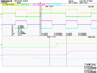
    The result of this code is captured on Oscilloscope as below (yellow - ADC ISR GPIO45 & green is ISR flag-GPIO88, rest 2 are PWM2A and PWM2B), the question is why green is arriving after yellow ? should not green be starting before yellow?  because ADC ISR should arrive at EOC12. 

    Best, 

  • Hi, 

    From looking at the code in ADC_ISR, it seems clear that GPIO45 will be set before GPIO88 is toggled. I think the code where you are polling ADCSOCFLG1 is not working correctly. 

    If you only want to measure the time taken to do these conversions, I recommend this simple procedure:

    1. Software trigger SOC0-SOC12

    2. Toggle GPIO45

    3. Have some way to wait for ADC conversions to finish, possibly by waiting until ADCINT flag is set

    4. Toggle GPIO45 again

    This is basically what is done in our ADC software trigger (ex1) examples. 

    Best Regards,

    Ben Collier