


Tool/software:
Hi champs,
I am asking this for our customer.
About the app note, spracw9a, "Methods for Mitigating ADC Memory Cross-Talk" in
The user has questions:
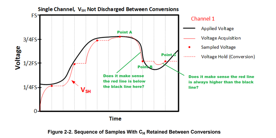
1) From Point A to Point B, does it make sense the red line can be below the black line? That is, why the red line (Ch) can be lower than the real applied voltage?
2) From Point B to Point C, does it make sense the red line is always higher than the black line? That is, the user thinks the red line should drop (discharge) below the black line first and then go up (charge) but still below the black line.
What do you think?
3) Similarly, from point D to point E, does it make sense the blue (acquisition) is always lower than the channel 2 applied voltage? The user thinks it should be higher than channel 2 applied voltage and then drop after channel 2 applied voltage drops.
4) From point E to point F, does it make sense the red (acquisition) is always lower than the channel 1 applied voltage? The user thinks it should be going higher than channel 1 applied voltage and then drop after channel 2 applied voltage drops but still higher than applied voltage.
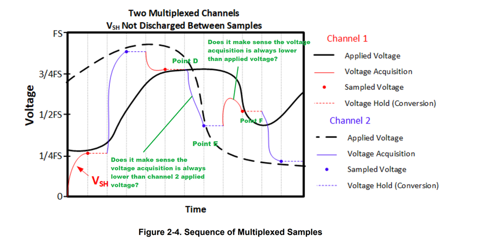
That is, the user thinks the voltage acquisition should follow and run after the applied voltage with phase delay rather than drop or rise before the applied voltage. Do you have any comment?
