This thread has been locked.

If you have a related question, please click the "Ask a related question" button in the top right corner. The newly created question will be automatically linked to this question.

TMS320F28379D: OUTPUTXBAR: Unable to set and clear the OUTPUTLATCH using OUTPUTLATCHCLR when the input remains one for the latch

Part Number: TMS320F28379D


Tool/software:

I am using OUTPUT XBAR and I am passing a CMPSS trip out to it. The CMPSS CTRIPOUTH is 1 and this is passed to the OUTPUTx via the D Latch for OUTPUT XBAR

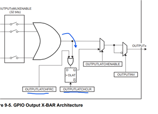
Here is my problem: When I try to clear the LATCH output via OUTPUTLATCHCLR register, it remains 1 as is and does not clear out.
When I disable the OUTPUTxMUXENABLE register and then clear the latch via setting OUTPUTLATCHCLR to 1, it gets cleared.

For the D latch, the expected behavior is that when OUTPUTLATCHCLR is set to 1, the output gets cleared regardless of the clock or data input. But here, I see that it gets cleared only when the input is set to 0. It is not cleared when input is 1. 

Is this correct behavior or am I understanding things incorrectly?

I also saw that the following is written for the OUTPUTLATCH register:

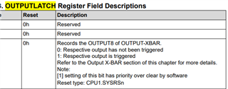
Does it mean that if the input setting is '1' for the latch, it has a higher priority over clearing the latch output using OUTPUTLATCHCLR?

Does it mean that if the input is 1, we cannot clear the latch using OUTPUTLATCHCLR, and only when the input is 0, we can clear it? Won't this defeat the purpose of the D latch?

  • Hey Sumukh,

    We have recieved you query and are looking into it now. Please expect a response by Tuesday 6/10/25. Thank you for your patience.

    Best Regards,

    Zackary Fleenor

  • Hey Sumukh,

    I wanted to provide an update. I am still working on this with the team. Will need till (06/13/25) to formulate the proper response. 

    Best Regards,

    Zackary Fleenor

  • Hey Sumukh,

    Can you verify that you have set OUTPUTLATCHENABLE to 1 during this testing

    I also wanted to provide some clarification here.

    The OUTPUTLATCHCLR bitfield is W1TS Write One to Set, this means that after the bitfield is set to to 1 by SW, it is immediately reset to 0 by HW. As you have shown in the screenshot, the input setting of OUTPUTLATCH has priority over the OUTPUTLATCHCLR function and on the following clock cycle the input value will be latched again.

    What is your application/use-case expectations for the use of the OUTPUTLATCH functionality? 

    Best Regards,

    Zackary Fleenor