LAUNCHXL-F28P55X: Current Control in BUILDLEVEL FCL_LEVEL3

Part Number: LAUNCHXL-F28P55X
Other Parts Discussed in Thread: BOOSTXL-3PHGANINV, INA240

Tool/software:

I'm using BoostXL3PhGaN with LAUNCHXL-F28P55X. The project is dual_axis_servo_drive.

I am following these steps:

---------------------------------------------------------------------------------------------------------------------------------------------------------------------------------------------------------------------------------------------------------------------------------------

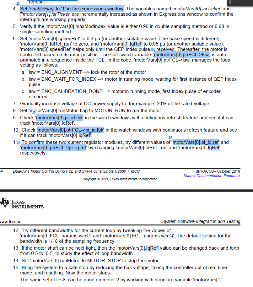
1) Set 'motorVars[0].speedRef' to 0.3 pu (or another suitable value if the base speed is different) .. 'motorVars[0].speedRef' helps only until the QEP index pulse is received. Thereafter, the motor is controlled based on its rotor position.

Tell me if I have understood correctly: after the encoder calibration (so when lsw = ENC_CALIBRATION_DONE) motorVars[0].speedRef no longer has any effect, so I no longer need it. Right?

------------------------------------------------------------------------------------------------------------------------------------------------------------------------------------------------------------------------------------------------------------------------------------

2) If I have understood point 1) correctly ... how do I adjust the speed? Can it be done in FCL_LEVEL3? Or does it remain fixed?

------------------------------------------------------------------------------------------------------------------------------------------------------------------------------------------------------------------------------------------------------------------------------------

3) Gradually increase voltage at DC power supply to, for example, 20% of the rated voltage.

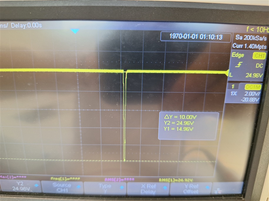
Is this step necessary? 20% is a value below the minimum threshold that triggers fault undervoltage ... why can't I debug and start directly with rated Vdc? I currently do this with Vdc=30V and have no problems.

------------------------------------------------------------------------------------------------------------------------------------------------------------------------------------------------------------------------------------------------------------------------------------

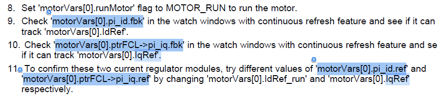
4) Set 'motorVars[0].IdRef_run' to zero, and 'motorVars[0].IqRef' to 0.05 pu (or another suitable value) and all these things:

This is what I get:

4a) Setting "motorVars[0].IdRef_run" improves (becomes more sinusoidal) and increases the waveform amplitude of the motor phase current and:
- "motorVars[0].IdRef"      follows IdRef_run   Thumbsup 
- "motorVars[0].pi_id.fbk" follows IdRef_run  Thumbsup 

..so I'd say everything is OK, right?

4b) Instead, by setting, "motorVars[0].IqRef":

- "motorVars[0].ptrFCL->pi_iq.fbk" does NOT follow IqRef  Thumbsdown

Why? Can you help me investigate this problem or what variables I should play with?

------------------------------------------------------------------------------------------------------------------------------------------------------------------------------------------------------------------------------------------------------------------------------------

5a) Test different values of "pMotor->FCL_params.wccD" and "pMotor->FCL_params.wccQ":

pMotor->FCL_params.wccD = M1_CUR_LOOP_BANDWIDTH;
pMotor->FCL_params.wccQ = M1_CUR_LOOP_BANDWIDTH;
M1_CUR_LOOP_BANDWIDTH = (2.0F * PI * M1_SAMPLING_FREQ / 100)
                      = (2.0F * PI * M1_PWM_FREQUENCY * 1000 / 100)
                      = (2.0F * PI * DM_PWM_FREQUENCY * 1000 / 100) = 628kHz using DM_PWM_FREQUENCY=10kHz

"The default setting for the bandwidth is 1/18 of the sampling frequency" but as you see in the code I get 638kHz .. which is not 1/18 di 10kHz

5b) I cannot find or set the parameters that the pdf asks me to change:

    1. Yes
    2. Build 3 is not primarily about the speed loop. Refer to build 4.
    3. The most important part of this instruction is not the value you're increasing to, but rather that you do it gradually. 20% is an example which (I believe) was for a higher voltage motor. For a lower voltage motor, setting the DC Bus Voltage to the rated voltage of the motor is typically fine.
    4. Looking into this currently. Does the value of pi_iq.fbk correspond to anything, or does it appear random?
    5. .
      1. First, notice the 2pi in the equation. the final result is not in Hz, but in radians. Second, notice that the bandwidth is M1_SAMPLING_FREQ / 100. Unless I'm mis-remembering the code, that means that the current loop bandwidth is 1/100 of the sampling frequency. I think the user's guide needs to be updated here as well.
      2. The names in the user's guide need to be updated. Let me double-check what the correct names are, apologies. I'll get back to you with this soon.

    Regards,
    Jason Osborn

  • 4b. Sometimes it works: motorVars[0].ptrFCL->pi_iq.fbk follows IqRef

    Other times, instead, pi_iq.fbk has random values (if it should be 0.1 ... it fluctuates randomly instead between 0.0023 and 0.0013)

    5a. Thanks for the clarification. So 628000 radians/s correspond to 100kHz bandwidth .. right?

    6. It has nothing to do with the current problem of point 4 ... but I tried adding a load to the motor, but I get the error pMotor->tripFlagDMC |= 0x0002 given by:

    if( (pMotor->Vdcbus > pMotor->VdcbusMax) || (pMotor->Vdcbus < pMotor->VdcbusMin) )
            pMotor->tripFlagDMC |= 0x0002;

    I tried with Id_ref = 0, then Iqref = 0.05 and 0.1 etc. but the motor (after encoder alignment) accelerates quickly and goes into fault almost immediately.

    I also tried setting Vdc = 20V, 30V and 40V but nothing change.

    These are the default values I have:

    In addition, I would like to ask you what the difference is between M1_MAXIMUM_VOLTAGE and M1_VDCBUS_MAX.

    This is the Vdc bus that I measure with the oscilloscope:

    I have a theoretical doubt:

    7) When I set IqRef>0 the motor rotates clockwise ... when I set IdRef>0 it rotates anticlockwise .. why?

    Iq should contribute to the torque while Id to the flow..

  • Apologies for the delay.

    • 4: Interesting. Good to know.
    • 5: 10kHz, not 100. 628,000 / (2pi) = ~10,000 (for the approximation of pi = 3.14)
    • 6: MAXIMUM_VOLTAGE is legacy code, assigned to the unused variable voltageLimit in the motor object. Minimum voltage isn't used at all. The _VDCBUS_ parameters represent the actual upper and lower limits for the DC bus voltage before an error is flagged.
      • I'll address the rest of (6) momentarily.
    • 7: Since this is the current controlled build level, I believe this is due to how the Id/IqRef values affect the startup routine in this build of the project- recall that there is no speed feedback loop. This shouldn't happen in the closed speed loop.

    Now, as for the error in (6), I'm going to say that it looks from the oscilloscope screenshot like the error is reporting accurately- your VDC shouldn't be dipping like that. Based on my prior experience and the context of the error, this most likely means that your power source is not currently sufficient to run the motor. High current draw and an unchanging maximum power means that your voltage is going to dip.

    Next, for WccD and WccQ, it was actually just a capitalization error. It's wccD and wccQ.

    Lastly, for Iq not following, try adjusting those parameters, like the guide suggests.

    Regards,
    Jason Osborn

  • 4. However, this behaviour is not normal, right? ..i.e. that the current feedback of Iq does not follow what I have set

    5. It seems to me that 628,000 / 6.28 = 100,000

    5b) By default, the bandwidht is set the same for both Q and D:

    .. I should then vary this value and study the behaviour of the motor, right? wccD and wccQ could be different?

    6. I tried again current control FCL_LELVEL 3 again (it had been a couple of weeks since I had tried it) but now the code is stuck at ENC_WAIT_FOR_INDEX, regardless of IqRef and IdRef_run values. I will do further tests, but if you already know what might be causing it please write to me, thank you

    7. In the closed loop speed control (FCL_LEVEL 4), once SpeedRef is set ... if I vary IdRef and IqRef speed/direction do not change (like you said). Maybe the torque should change, right?

    What I mean is that, although the control is in speed, if I apply a higher load that causes the motor to struggle ... I suppose there is some parameter (I think IqRef) that allows me to increase the current to the motor .. am I right??

  • Oh- I'm not sure what I misread last time, but I did misread something, you're right about the calculation, I'm so sorry about that. Not sure how I made a mistake like that.

    As for Iq, you're correct that that is not normal behavior based on our documentation. The fact that the not-working case appears random is good information to have for debug, which is why I said it was interesting.

    For your other questions, I'm going to point again at the power source. Until you resolve this issue, it's unlikely that you're going to get good performance for your motor and system, and it's possible you're not going to be able to get meaningful information at all from your testing. If it's possible to use a better power source, I'd recommend doing so.

    Regards,
    Jason Osborn

  • Thanks! I will continue testing as soon as my new power supply arrives ... if there are any problems I will come back here or open a new question

  • Hey luca seems like i'm also stuck at same level, I'm working on Boostxl-3phganinv sensored project, i'm too stuck at this stage there are two problems which i'm facing right know, one that it use LEM current sensor but mine is INA240 untill build there was no issue as we were not that much concerned about current readings but for build level 3 i  believe i need to fix it and second problem is same as you are facing untill build 2 my vdcbus is reading equal to what i'm supplying but at build level 3 it is reading 7v for 24v supply that is why tripflagDMC is setting as vdcbus <vdcbusMIN , please help me fix these.

    Thanks & Regards
    Abhay