Hello,
Googled a lot: "which I2C slave answered" and similar and couldn't find the answer!! :(
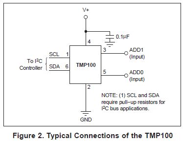
I have 2x TMP100 temperature sensors connected to 28335 .
They are working fine, separately, under different addresses, under interruption. I'd like to plug them together as multiple I2C slaves.
Now, since I am not polling, if I read temperatures of 1 sensor and then just following reading the other one, how can I know which one is answering first? What I mean is, although each one has unique addresses, if I don't stagger/alternate each sensor call timing, after the first one delivered his data, how I am to know for sure which one triggered ARDY interruption in first place?
Here is my code below, for just one sensor!
#include "DSP2833x_Device.h"
// TMP100 commands
#define TMP100_SLAVE 0x48 // slave address TMP100 (ADDR0=ADDR1=0)
#define POINTER_TEMPERATURE 0
#define POINTER_CONFIGURATION 1
#define POINTER_T_LOW 2
#define POINTER_T_HIGH 3
// external function prototypes
extern void InitSysCtrl(void);
extern void InitPieCtrl(void);
extern void InitPieVectTable(void);
extern void InitCpuTimers(void);
extern void ConfigCpuTimer(struct CPUTIMER_VARS *, float, float);
// Prototype statements for functions found within this file.
void Gpio_select(void);
void I2CA_Init(void);
interrupt void cpu_timer0_isr(void);
interrupt void i2c_fifo_isr(void);
interrupt void i2c_basic_isr(void);
//global variables:
int temperature; // temperature = 2' Komplement of temperature (-128 ... +127 Celsius)
// is an I8Q8 - Value
int I2C_Comm_Error=0;
//###########################################################################
// main code
//###########################################################################
void main(void)
{
InitSysCtrl(); // Basic Core Init from DSP2833x_SysCtrl.c
EALLOW;
SysCtrlRegs.WDCR = 0x68; // DISABLES WDT
EDIS; // 0x00AF to NOT disable the Watchdog, Prescaler = 64
DINT; // Disable all interrupts
Gpio_select();
I2CA_Init(); // Initialize I2C
// Send START, set pointer to Configuration register and set resolution to 12 bit
I2caRegs.I2CCNT = 2; // set count # in DSP to 2 bytes (i.e. for writing)
I2caRegs.I2CDXR = POINTER_CONFIGURATION;
I2caRegs.I2CDXR = 0x60; //set TMP100 Config. Register - 12 bits resolut.:
/*
OS/ALERT:
write 1: single temperature conversion
write 0: continuous temperature conversion
read 1: temperature above THIGH
read 0: temperature below TLOW
R1, R0:
Resolution 9 bit (0,0) … 12 bit (1,1)
F1,F0:
activate ALERT after number of consecutive faults (1,2,4,6)
POL:
Polarity of ALERT (0 or 1)
TM:
write 0: Comparator Mode (ALERT stays active as long as condition is true)
write 1: Interrupt Mode( ALERT is cleared by a read instruction of any reg)
SD:
write 1: shutdown
write 0: active mode
*/
I2caRegs.I2CMDR.all = 0x6E20; // Initialize register “I2CMDR”:
/*
Bit15 = 0; no NACK in receiver mode
Bit14 = 1; FREE on emulation halt
Bit13 = 1; STT generate START
Bit12 = 0; reserved
Bit11 = 1; STP generate STOP
Bit10 = 1; MST master mode
Bit9 = 1; TRX transmitter mode // if 0, receiver mode
Bit8 = 0; XA 7-bit address mode
Bit7 = 0; RM non-repeat mode, I2CCNT determines # of bytes
Bit6 = 0; DLB no loopback mode
Bit5 = 1; IRS I2C module enabled
Bit4 = 0; STB no start byte mode
Bit3 = 0; FDF no free data format
*/
while(I2caRegs.I2CSTR.bit.SCD == 0); //Wait for the successful generation of the stop-condition
I2caRegs.I2CSTR.bit.SCD = 1; //Clear the stop condition flag
InitPieCtrl(); // basic setup of PIE table; from DSP2833x_PieCtrl.c
InitPieVectTable(); // default ISR's in PIE
// load addresses of interrupt service routines into the PieVectTable
EALLOW;
PieVectTable.TINT0 = &cpu_timer0_isr;
PieVectTable.I2CINT2A = &i2c_fifo_isr;
PieVectTable.I2CINT1A = &i2c_basic_isr;
EDIS;
InitCpuTimers(); // basic setup CPU Timer0, 1 and 2
ConfigCpuTimer(&CpuTimer0,150,100000); // CPU - Timer0 at 100 milliseconds
PieCtrlRegs.PIEIER1.bit.INTx7 = 1; //timer0
PieCtrlRegs.PIEIER8.bit.INTx1 = 1; // i2c - basic
PieCtrlRegs.PIEIER8.bit.INTx2 = 1; // i2c - FIFO
//IER |=1;
IER |=0x81; //register IER must now allow lines INT1 and INT8 for i2c basic and fifo interrupts
EINT;
ERTM;
CpuTimer0Regs.TCR.bit.TSS = 0; // start timer0
while(1)
{
if(CpuTimer0.InterruptCount != 0) //returning from INT Timer0
{
CpuTimer0.InterruptCount = 0;
GpioDataRegs.GPBTOGGLE.bit.GPIO34 = 1; // toggle red LED LD3 @ 28335CC
GpioDataRegs.GPATOGGLE.bit.GPIO31 = 1;
//configure TMP101 for reading temperatures. Send START and set pointer to temperature - register
I2caRegs.I2CCNT = 1; // 1 byte message
I2caRegs.I2CDXR = POINTER_TEMPERATURE;
I2caRegs.I2CMDR.all = 0x6620; // master-transmitter
// master - receiver mode is initialized in "i2c_basic_isr" after ARDY
// read of temperature is done by ISR "i2c_fifo_isr"
}
/*
EALLOW;
SysCtrlRegs.WDKEY = 0x55; // service WD #1
EDIS;
*/
}
}
void Gpio_select(void)
{
EALLOW;
GpioCtrlRegs.GPAMUX1.all = 0; // GPIO15 ... GPIO0 = General Puropse I/O
GpioCtrlRegs.GPAMUX2.all = 0; // GPIO31 ... GPIO16 = General Purpose I/O
GpioCtrlRegs.GPBMUX1.all = 0; // GPIO47 ... GPIO32 = General Purpose I/O
GpioCtrlRegs.GPBMUX1.bit.GPIO32 = 1; // GPIO32 = I2C - SDA
GpioCtrlRegs.GPBMUX1.bit.GPIO33 = 1; // GPIO33 = I2C - SCL
GpioCtrlRegs.GPBPUD.bit.GPIO32 = 0; // Enable pull-up for GPIO32 (SDAA)
GpioCtrlRegs.GPBPUD.bit.GPIO33 = 0; // Enable pull-up for GPIO33 (SCLA)
GpioCtrlRegs.GPBQSEL1.bit.GPIO32 = 3; // Asynch input GPIO32 (SDAA)
GpioCtrlRegs.GPBQSEL1.bit.GPIO33 = 3; // Asynch input GPIO33 (SCLA)
GpioCtrlRegs.GPBMUX2.all = 0; // GPIO63 ... GPIO48 = General Purpose I/O
GpioCtrlRegs.GPCMUX1.all = 0; // GPIO79 ... GPIO64 = General Purpose I/O
GpioCtrlRegs.GPCMUX2.all = 0; // GPIO87 ... GPIO80 = General Purpose I/O
GpioCtrlRegs.GPADIR.all = 0; // GPIO0 to 31 as inputs
GpioCtrlRegs.GPADIR.bit.GPIO31 = 1; // GpIO31 = LED LD2
GpioCtrlRegs.GPBDIR.all = 0; // GPIO63-32 as inputs
GpioCtrlRegs.GPBDIR.bit.GPIO34 = 1; // LED LD3 at GPIO34
GpioCtrlRegs.GPCDIR.all = 0; // GPIO87-64 as inputs
EDIS;
}
void I2CA_Init(void)
{
I2caRegs.I2CMDR.bit.IRS = 0; // Reset the I2C module
I2caRegs.I2CSAR = TMP100_SLAVE; // I2C slave address register
// I2C Prescale Register
I2caRegs.I2CPSC.all = 14; // Internal I2C module clock = SYSCLK/(PSC +1)
// = 10 MHz
// Setting I2C-clock frequency of 50 kHz (clock period = 20us). Ver eq. abaixo.
I2caRegs.I2CCLKL = 95; // Tmaster = (PSC +1)[ICCL + 5 + ICCH + 5] / 150MHz
I2caRegs.I2CCLKH = 95; // Tmaster = 15 [ICCL + ICCH + 10] / 150 MHz
// d = 5 for IPSC >1
// for I2C 50 kHz:
// Tmaster = 20 µs * 150 MHz / 15 = 200 = (ICCL + ICCH +10)
// ICCL + ICCH = 190
// ICCL = ICH = 190/2 = 95
// I2caRegs.I2CCLKL = 45;
// I2caRegs.I2CCLKH = 45; // for I2C 100 kHz:
// Tmaster = 10 µs *150 MHz / 15 = 100 = (ICCL + ICCH + 10)
// ICCL + ICCH = 90
// ICCL = ICH = 90/2 = 45
I2caRegs.I2CIER.bit.ARDY = 1; //enable basic I2C-interrupt - access ready, which is generated, when the first two bytes of the “TMP100 Read Timing” I2C - data frame (see Slide 12-31) are transmitted.
I2caRegs.I2CIER.bit.NACK = 1; //enables I2C NACK interrupt: communication error handling
I2caRegs.I2CFFTX.all = 0; //I2C Transmit FIFO Register
I2caRegs.I2CFFTX.bit.TXFFIL = 0; //set the transmit interrupt level (bit field TXFFIL) to zero
I2caRegs.I2CFFTX.bit.I2CFFEN = 1; //Enable the FIFOs
I2caRegs.I2CFFTX.bit.TXFFRST = 1; //Enable the FIFO-transmit support
I2caRegs.I2CFFRX.all = 0; //I2C Receive FIFO Register
I2caRegs.I2CFFRX.bit.RXFFIL = 2; //set the receive interrupt level (bit field RXFFIL) to 2, because we will receive a 2 byte temperature message from the TMP100
I2caRegs.I2CFFRX.bit.RXFFRST = 1; //Enable the FIFO-receiver support
I2caRegs.I2CFFRX.bit.RXFFIENA = 1; //enable interrupt after receiving two temperature bytes from the TMP100
I2caRegs.I2CMDR.bit.IRS = 1; //Take I2C out of reset
}
interrupt void cpu_timer0_isr(void)
{
CpuTimer0.InterruptCount++;
//EALLOW;
//SysCtrlRegs.WDKEY = 0xAA; // service WD #2
//EDIS;
PieCtrlRegs.PIEACK.all = PIEACK_GROUP1;
}
interrupt void i2c_fifo_isr(void)
{
int i;
if (I2caRegs.I2CFFRX.bit.RXFFINT == 1) // RX-FIFO - interrupt
{
i = I2caRegs.I2CDRR << 8; // read upper 8 bit (integers)
i += I2caRegs.I2CDRR; // add lower 8 bit (fractions)
temperature = i;
I2caRegs.I2CFFRX.bit.RXFFINTCLR = 1; // clear ISR
}
PieCtrlRegs.PIEACK.all = PIEACK_GROUP8;
}
interrupt void i2c_basic_isr(void)
{
unsigned int IntSource;
IntSource = I2caRegs.I2CISRC.all; //make a local copy of this register - first read of this register will clear it automatically. It is good practice and will be very important later, when you enable more than one basic source,
if (IntSource == 3) // ARDY was source of interruption
{
I2caRegs.I2CCNT = 2; // read 2 byte temperature
I2caRegs.I2CMDR.all = 0x6C20; // Master-Receiver-Mode. Details of I2CMDR in main
}
if (IntSource == 2) // NACK was source of interruption - Communication Error
{
I2caRegs.I2CMDR.bit.STP = 1; // send STP to end transfer
I2caRegs.I2CSTR.bit.NACK = 1; // clear NACK bit
I2C_Comm_Error++;
}
PieCtrlRegs.PIEACK.all = PIEACK_GROUP8;
}
//===========================================================================
// End of SourceCode.
//===========================================================================
Tks!!