This thread has been locked.

If you have a related question, please click the "Ask a related question" button in the top right corner. The newly created question will be automatically linked to this question.

How To Evaluate and Develop with InstaSPIN-FOC and InstaSPIN-MOTION

Other Parts Discussed in Thread: TMDSHVMTRINSPIN, TMDSCNCD28027F, DRV8301-69M-KIT, LAUNCHXL-F28027F, BOOSTXL-DRV8301, TMS320F28027F, LAUNCHXL-F28069M, TMS320F28069M, MOTORWARE, CONTROLSUITE, CCSTUDIO, DRV8301, DRV8312, HVPMSMMTR, INSTASPINUNIVERSALGUI

Here is our recommendation for developing with InstaSPIN

Assuming you have already used the InstaSPIN website, the InstaSPIN simulation, and read through the Technical Reference Manuals (links on website)

to convince yourself that InstaSPIN-FOC and/or -MOTION are the right solution for you...

  1. Purchase an evalution kit
    1. TMDSHVMTRINSPIN
      1. includes TMDSCNCD28069MISO and TMDSCNCD28027F controlCARDs
    2. DRV8301-69M-KIT
      1. includes TMDSCNCD28069MISO
      2. you can purchase separately TMDSCNCD28027F which also requires the use of an external emulator (your choice: XDS100V2, XDS510, isolation recommended)
    3. DRV8312-69M-KIT
      1. includes TMDSCNCD28069MISO
      2. you can purchase separately TMDSCNCD28027F which also requires the use of an external emulator (your choice: XDS100V2, XDS510, isolation recommended)
    4. LAUNCHXL-F28027F + BOOSTXL-DRV8301
      1. Isolated XDS100v2 LaunchPad with InstaSPIN-FOC enabled TMS320F28027F
      2. BoosterPack for 6-24V, 10A continuous three phase motors
    5. LAUNCHXL-F28069M + BOOSTXL-DRV8301
      1. Isolated XDS100v2 LaunchPad with InstaSPIN-FOC and -MOTION enabled TMS320F28069M
      2. BoosterPack for 6-24V, 10A continuous three phase motors
  2. Install latest version of www.ti.com/tool/motorware 
  3. Run MotorWare.ex from the install location, ex: C:\ti\motorware\MotorWare_1_01_00_11\MotorWare.exe
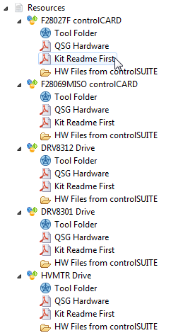
  • Each kit which includes a 69M devices has a CD with "kit contents". The latest version of these kit contents is always here. The 27F and Launchpad based kits have Universal GUI support with latest version always here.
  • Download and unzip this file and note the contents:
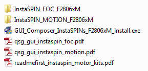
  • Read and follow "readmefirst_instaspin_motor_kits.pdf"
    • This document is also included in MotorWare.exe, linked with every piece of hardware.
    • Also note the location of the QSG Hardware document for each piece of hardware, these should be reviewed as you set-up the kits
  1. The hardware design files are kept in controlSUITE (C2000 MCU main product support) to keep the MotorWare installation smaller. Install controlSUITE if you want to access these files.

GUI Evaluation

  1. Follow the "qsg_gui_instaspin_foc.pdf" or "_motion.pdf" or "qsg_gui_universal.pdf"
    1. This includes running the GUI Composer installer which installs the standalone run-time
  2. If needed, view the GUI training videos
  1. InstaSPIN-FOC GUI Overview
  2. InstaSPIN-MOTION GUI Overview
  3. InstaSPIN-FOC LaunchPad and BoosterPack (Universal GUI) Series 

Evaluate the MotorWare projects and start learning about the software architecture, code structure, and API interface

  1. install the latest version of CCStudio from the included DVD or from the wiki site.
  2. Ensure that you are using compiler 6.2.3 or newer. There is a MAJOR BUG in compilers 6.2.0-6.2.2 DO NOT USE
  3. Follow the Projects & Lab User's Guide in MotorWare.exe
  4. CCS notes
  • Be sure that when you import the projects you do NOT select "Copy projects into workspace" option. We recommend working out of the MotorWare installation directory. This will make it much simpler to keep up with future revisions.
  • Do NOT change any of the project settings. Ex: you do NOT need to change the General --> Variant option to a specific device. This just selects a pre-installed .cmd file that will NOT work with the MotorWare projects.  The .cmd files included in MotorWare are already attached to the projects.
  • The general path for using CCS and MotorWare projects
  1. Import projects
  2. Make changes to user.h or the project .c as required
  3. Build selected project
  4. Set-up Target Configuration (emulator and device)
    1. XDS100v2 + F28069 (all kits)
    2. XDS100v1 + F28027 (HVMTR kit)
    3. XDS100v2 + F28027 (LaunchPad)
    4. your emulator + F28027 (DRV kits)
  5. Launch Target Configuration
  6. Connect Target
  7. Load Program you built in 3.
  8. Turn on real-time debug
  9. Run
  10. Set-up Expressions View using the .js file for that project
  11. Interface to software using Expressions
    1. Starting in release _10 you can also use new Universal GUI inside CCS to instrument variable

  • As you work through the labs, consult the appropriate sections of the InstaSPIN-FOC & -MOTION User's Guide for further details
    1. Ex: when working through lab 2 you will want to review the Motor Identification chapter of the UG to understand exactly what is happening and the options you have to make changes.
  • If you want to start your own project based on a MotorWare example, a method for doing so that allows portability as we release new revisions (~2-4 times per year planned) is outlined in this post.

After evaluation and initial software development, prepare your own hardware

  1. Be sure to follow the guidance in the User's Guide regarding analog sense circuitry design


  • Thanks Chris.  I finally got it up and running.  It turns out the customer's USB port was bad so it wouldn't connect.  When it finally connected, moving the mouse bumped the USB cable and it disconnected.  That's when I realized either I had a bad USB cable or the port was bad.

    I'm through lab01 which means my installation is complete and I'm ready to go spin a motor.  I hope I can remember enough.

  • Hi Chris,

    I'm ready to start but I wanted to touch base before I try to run the motor.

    1. The motor is not a PM motor.  I have a wound field on the rotor that should act like a PM once I energize the field.  I don't see anything that addresses this in the SW so I'm assuming that this is the same as a PM motor.

    2. The motor is designed for 250 amps under load.  We're just going to try to run it with no load.  I don't expect to pull more than 20 amps.

    3. Max speed is 6000 RPM but I only intend to try to get to about 3000 rpm unless all goes well (current draw will dictate if I go further).

    The stator is a delta with about 0.1 ohms from phase to phase and 389 mH phase inductance.  I have attached my initial spreadsheet.  Any comments?6378.motorware_selecting_user_variables.xlsx

  • This is the way My_Motor is set up in the code.


    #elif (USER_MOTOR == My_Motor)
    #define USER_MOTOR_TYPE MOTOR_Type_Pm
    #define USER_MOTOR_NUM_POLE_PAIRS (4)
    #define USER_MOTOR_Rr (NULL)
    #define USER_MOTOR_Rs (0.3918252)
    #define USER_MOTOR_Ls_d (0.00023495)
    #define USER_MOTOR_Ls_q (0.00023495)
    #define USER_MOTOR_RATED_FLUX (0.03955824)
    #define USER_MOTOR_MAGNETIZING_CURRENT (NULL)
    #define USER_MOTOR_RES_EST_CURRENT (10.0)
    #define USER_MOTOR_IND_EST_CURRENT (-10.0)
    #define USER_MOTOR_MAX_CURRENT (40.0)
    #define USER_MOTOR_FLUX_EST_FREQ_Hz (20.0)
    #define IPD_HFI_EXC_FREQ_HZ (750.0) // excitation frequency, Hz
    #define IPD_HFI_LP_SPD_FILT_HZ (10.0) // lowpass filter cutoff frequency, Hz
    #define IPD_HFI_HP_IQ_FILT_HZ (20.0) // highpass filter cutoff frequency, Hz
    #define IPD_HFI_KSPD (31.4) // the speed gain value
    #define IPD_HFI_EXC_MAG_COARSE_PU (0.2) // coarse IPD excitation magnitude, pu
    #define IPD_HFI_EXC_MAG_FINE_PU (0.2) // fine IPD excitation magnitude, pu
    #define IPD_HFI_EXC_TIME_COARSE_S (0.2) // coarse wait time, sec max 0.64
    #define IPD_HFI_EXC_TIME_FINE_S (0.1) // fine wait time, sec max 0.4
    #define AFSEL_FREQ_HIGH_PU (_IQ(20.0 / USER_IQ_FULL_SCALE_FREQ_Hz))
    #define AFSEL_FREQ_LOW_PU (_IQ(10.0 / USER_IQ_FULL_SCALE_FREQ_Hz))
    #define AFSEL_IQ_SLOPE_EST (_IQ((float)(1.0/0.1/USER_ISR_FREQ_Hz)))
    #define AFSEL_IQ_SLOPE_HFI (_IQ((float)(1.0/1.0/USER_ISR_FREQ_Hz)))
    #define AFSEL_IQ_SLOPE_THROTTLE_DWN (_IQ((float)(1.0/0.05/USER_ISR_FREQ_Hz)))
    #define AFSEL_MAX_IQ_REF_EST (_IQ(0.4))
    #define AFSEL_MAX_IQ_REF_HFI (_IQ(0.4))
  • I'd set
    USER_MOTOR_FLUX_EST_FREQ_Hz (40.0)

    and just leave the Rs, Ls, and Flux values NULL until you ID.

    You should get an Rs of around 0.05 ohm.
  • Thanks for everything Chris. The motor characterized and spins. I am curious as to why my inductance is 45uH when it's supposed to be hundreds of mH. Is the actual measured inductance usually 4 orders of magnitude different with the tool? I'll double check on my end to make sure that the 389 mH is correct.
  • I have some final questions.

    1. The SpeedRef_krpm is 1677721 when the motor is spinning about 60 rpm. This is with the number format set to decimal. I thought the last time I used this the speed variable was more usable than that.

    2. I thought before when I used this that I had a lab that let me control the speed by changing the input. I see lab05b where they go into tuning the PI speed loop but I'm a long way from that stage.

    Like usual, once you get over the nightmare of installation and set up, you can spin a motor in a very short time. Now it's time to start reading so I can build a design so we can move forward.

    Thanks again.
  • 1. no, per the lab guide you should use the .js file to fill in the Expressions. It will set most variables to IQ24
    2. which input? all of the labs allow changing the speed from the gMotorVars variable. There is a tutorial in MotorWare on how to hook up the potentiometer to vary a speed.

    what were the other USER_MOTOR values IDd?

    The Ls from your datasheet is certainly some factor larger than what we identify, but either by a value of 2 (line to neutral) or 3 (line to neutral and delta connected). If you have an LCR meter try line to line at 100 Hz and see if you actually get 300+ mH. It could also be effected by the IND_EST_CURRENT of (-10.0) and the FLUX_EST_FREQ of (40.0) . You can try to vary these and see if it changes things much.
  • Hi Chris,

    1. Unfortunately, the lab guide no longer matches the tools (see my rant at the beginning).  The lab guide tells me to set the number format and of course, the picture no longer matches what comes up in the Watch Window.  I could figure out most so I set what I could.  Incidentally, they do not come up correct.  Some of them have to be set.

    2. I saw the potentiometer on the kit but I've never seen the instructions to use it.  Of course, I've never really gotten to complete these labs so I don't know where it comes into play.  I just changed one of the gMotorVars.Speed_krpm (there are about 3 of these with similar names, I can't remember which one I used) values in the Watch Window and the speed follows.  I thought I tried the Q-Value(24) but I'll try it again and see if the data makes any sense.

    I'm going to try to find an LCR meter today to measure the actual inductance.  What do you recommend for the  IND_EST_CURRENT  and the FLUX_EST_FREQ values if my inductance is 300+mH?  Or, should I just get back to you when I find out.

    Thanks for all the help so far.  This solution for spinning a motor is truly awesome. It's a major shame that figuring out what you need, downloading (one at a time at snail speeds?) installing the right version of the software, finding the instructions, and deciphering the instructions (which were written for version x when you're using version y tools) is such a nightmare.

  • I tried posting a response earlier but this software ate it.

    1. Unfortunately, the lab guide doesn't match the tools (see my opening rant).  The lab guide tells me to set the number format if it isn't decimal for the first few variables and Q-Value(24) for some others.  They are not correct out of the box.  Also, the list in the figure is not the same as what is displayed in the Watch Window.  Therefore, I had to wing it.  I thought I tried the Q-Value(24) for the speed variables and it didn't work either.  I'll try it again.

    2. I've never found anything in the lab guide that refers to a potentiometer.  I did a search for potentiometer this morning and came up with zip.  The variable I used was gMotorVars.SpeedRef_krpm.  I set a speed and the motor responded.  This morning I looked through the two speed chapters in the lab guide and the only thing I saw that the lab guide recommended setting for controlling the speed was gMotorVars.SpeedRef_krpm. Again, I found no reference to the potentiometer,.

    3. I'm not sure what you want for the "other USER_MOTOR values IDd".  I have not been out to the lab since I posted last.  When I go out this time I'll record all the values.

    The TI solution to run a motor is superb.  After 3 days of frustration just to get the correct versions of the software installed and set up (talking to the kit), I had characterized and was running the motor in 15 minutes. It's a pity TI didn't see fit to give the users proper instructions (on the web site where you get the data and buy the tool) as to what to download (i.e. what you NEED, not everything), instructions on how to install the software (I'm referring to the "Do you want to install the blah add-ins", not the normal installation screens), which versions to actually install (given it takes 2 days to download and install the software), instructions on where to find the instructions to run the labs and tools, and instructions that actually match the version of the tools and labs you're working with.

    Hopefully this forum software won't eat this post.  I'm backing it up just in case.

  • It looks like the forum tool actually took the post. Anyway, I went out to the lab this morning to demonstrate we can run the motor. The motor runs perfectly at any speed up to 2000 rpm. The motor won't run over 2000 rpm even though the software (motor speed in the watch window - I think it is gMotorVars.Speed_krpm) 'indicates' it is running at the set speed above 2000. I'm trying to find an LCR meter to measure the motor windings. I'll get back to you when I get data.

    Incidentally, when I used this kit at another company (THIS kit as it is my kit) on other motors, I could spin them over 10,000 rpm and the variables and tachometer agreed on the speed. The tachometer was a contact type, not a strobe type so there was no question as to harmonic error. Here, I'm using a strobe type tachometer but you can tell there is no change in speed when the motor is stepped from 2000 rpm to 6000 rpm. The tach also shows nothing happening. The gMotorVars.Speed_krpm variable ramps up until it agrees with the command gMotorVars.SpeedRef_krpm.

    First I want to make sure my motor matches the characterized L and R values (at least reasonably). The designer told us it was 390 mH but that's a very, very long way from what the characterization says. I've put a cheap LCR meter on the motor and I'm seeing around 100 uH which is more in the range of what the characterization says. This is not a good meter so I'm looking for a better one. The phase to phase readings vary by about 2 to 1 from phase to phase so I'm hoping it's the meter, not the motor.
  • Hi Chris,

    Here's the data:

    Actual measured inductance from phase to phase is about 130 uH.  This leads to actual inductance being about 200 uH per winding in delta configuration.

    Actual measured resistance from phase to phase is about 23 mohm => 35 mohms per winding in delta configuration.

    I don't know calculate in your program yet.

    Here are the results of lab 3b:

  • if you just expand gMotorVars then yes, you need to set the number type.
    If you use the Scripting console and run the proj_lab##.js it will import the variables required for that lab with the proper number type. This is in the instructions.

    you can also install INSTASPINUNIVERSALGUI
    and follow the instructions from
    C:\ti\motorware\motorware_1_01_00_16\docs\guis\universal\qsg_gui_universal.pdf

    on how to use this GUI inside of CCS. That's what I do and I find it easier than using the variables in the Expressions.

    regarding your motor parameters, I trust the motor ID function (and your LCR meter) more than the motor designer.

    use proj_lab02c to ID the motors and store in USER_MOTOR section of user.h per the instructions.
  • [Start: Texas Instruments XDS100v2 USB Debug Probe_0]
    
    Execute the command:
    
    %ccs_base%/common/uscif/dbgjtag -f %boarddatafile% -rv -o -F inform,logfile=yes -S pathlength -S integrity
    
    [Result]
    
    
    -----[Print the board config pathname(s)]------------------------------------
    
    C:\Users\lenovo\AppData\Local\TEXASI~1\CCS\
        ti\0\0\BrdDat\testBoard.dat
    
    -----[Print the reset-command software log-file]-----------------------------
    
    This utility has selected a 100- or 510-class product.
    This utility will load the adapter 'jioserdesusb.dll'.
    The library build date was 'Feb 13 2017'.
    The library build time was '16:06:25'.
    The library package version is '6.0.576.0'.
    The library component version is '35.35.0.0'.
    The controller does not use a programmable FPGA.
    The controller has a version number of '4' (0x00000004).
    The controller has an insertion length of '0' (0x00000000).
    This utility will attempt to reset the controller.
    This utility has successfully reset the controller.
    
    -----[Print the reset-command hardware log-file]-----------------------------
    
    The scan-path will be reset by toggling the JTAG TRST signal.
    The controller is the FTDI FT2232 with USB interface.
    The link from controller to target is direct (without cable).
    The software is configured for FTDI FT2232 features.
    The controller cannot monitor the value on the EMU[0] pin.
    The controller cannot monitor the value on the EMU[1] pin.
    The controller cannot control the timing on output pins.
    The controller cannot control the timing on input pins.
    The scan-path link-delay has been set to exactly '0' (0x0000).
    
    -----[The log-file for the JTAG TCLK output generated from the PLL]----------
    
    There is no hardware for programming the JTAG TCLK frequency.
    
    -----[Measure the source and frequency of the final JTAG TCLKR input]--------
    
    There is no hardware for measuring the JTAG TCLK frequency.
    
    -----[Perform the standard path-length test on the JTAG IR and DR]-----------
    
    This path-length test uses blocks of 64 32-bit words.
    
    The test for the JTAG IR instruction path-length failed.
    The JTAG IR instruction scan-path is stuck-at-ones.
    
    The test for the JTAG DR bypass path-length failed.
    The JTAG DR bypass scan-path is stuck-at-ones.
    
    -----[Perform the Integrity scan-test on the JTAG IR]------------------------
    
    This test will use blocks of 64 32-bit words.
    This test will be applied just once.
    
    Do a test using 0xFFFFFFFF.
    Scan tests: 1, skipped: 0, failed: 0
    Do a test using 0x00000000.
    Test 2 Word 0: scanned out 0x00000000 and scanned in 0xFFFFFFFF.
    Test 2 Word 1: scanned out 0x00000000 and scanned in 0xFFFFFFFF.
    Test 2 Word 2: scanned out 0x00000000 and scanned in 0xFFFFFFFF.
    Test 2 Word 3: scanned out 0x00000000 and scanned in 0xFFFFFFFF.
    Test 2 Word 4: scanned out 0x00000000 and scanned in 0xFFFFFFFF.
    Test 2 Word 5: scanned out 0x00000000 and scanned in 0xFFFFFFFF.
    Test 2 Word 6: scanned out 0x00000000 and scanned in 0xFFFFFFFF.
    Test 2 Word 7: scanned out 0x00000000 and scanned in 0xFFFFFFFF.
    The details of the first 8 errors have been provided.
    The utility will now report only the count of failed tests.
    Scan tests: 2, skipped: 0, failed: 1
    Do a test using 0xFE03E0E2.
    Scan tests: 3, skipped: 0, failed: 2
    Do a test using 0x01FC1F1D.
    Scan tests: 4, skipped: 0, failed: 3
    Do a test using 0x5533CCAA.
    Scan tests: 5, skipped: 0, failed: 4
    Do a test using 0xAACC3355.
    Scan tests: 6, skipped: 0, failed: 5
    Some of the values were corrupted - 83.3 percent.
    
    The JTAG IR Integrity scan-test has failed.
    
    -----[Perform the Integrity scan-test on the JTAG DR]------------------------
    
    This test will use blocks of 64 32-bit words.
    This test will be applied just once.
    
    Do a test using 0xFFFFFFFF.
    Scan tests: 1, skipped: 0, failed: 0
    Do a test using 0x00000000.
    Test 2 Word 0: scanned out 0x00000000 and scanned in 0xFFFFFFFF.
    Test 2 Word 1: scanned out 0x00000000 and scanned in 0xFFFFFFFF.
    Test 2 Word 2: scanned out 0x00000000 and scanned in 0xFFFFFFFF.
    Test 2 Word 3: scanned out 0x00000000 and scanned in 0xFFFFFFFF.
    Test 2 Word 4: scanned out 0x00000000 and scanned in 0xFFFFFFFF.
    Test 2 Word 5: scanned out 0x00000000 and scanned in 0xFFFFFFFF.
    Test 2 Word 6: scanned out 0x00000000 and scanned in 0xFFFFFFFF.
    Test 2 Word 7: scanned out 0x00000000 and scanned in 0xFFFFFFFF.
    The details of the first 8 errors have been provided.
    The utility will now report only the count of failed tests.
    Scan tests: 2, skipped: 0, failed: 1
    Do a test using 0xFE03E0E2.
    Scan tests: 3, skipped: 0, failed: 2
    Do a test using 0x01FC1F1D.
    Scan tests: 4, skipped: 0, failed: 3
    Do a test using 0x5533CCAA.
    Scan tests: 5, skipped: 0, failed: 4
    Do a test using 0xAACC3355.
    Scan tests: 6, skipped: 0, failed: 5
    Some of the values were corrupted - 83.3 percent.
    
    The JTAG DR Integrity scan-test has failed.
    
    [End: Texas Instruments XDS100v2 USB Debug Probe_0]
    

    Hi Chris

    Thanks for the very elaborate instructions. It's a life saver.

    I opened the code present in

    C:\ti\motorware\motorware_1_01_00_17\sw\solutions\instaspin_foc\boards\boostxldrv8301_revB\f28x\f2806xF\projects\ccs5\proj_lab01

    Compiled it in ccs 7.0, but i have problems connecting to target.

    I had to choose a processor (28069M and XDSv2 as connection) I have a big "test connection report".  

    What do i do ?

    Regards

    Srinath

  • Srinath,

    Please create a new thread for us to better attend to your question, we do not wish to support issues in old threads such as this.

    Sean