This thread has been locked.

If you have a related question, please click the "Ask a related question" button in the top right corner. The newly created question will be automatically linked to this question.

Overmodulation and other questions

Other Parts Discussed in Thread: LAUNCHXL-F28027F, BOOSTXL-DRV8301, MOTORWARE, TIDA-00643, DRV8312

I have been playing around with motoware on the LAUNCHXL-F28027F + BOOSTXL-DRV8301 platform for a while now.  For the most part I am coming to terms with it.  However I am left with several questions I haven't been able to solve to my satifaction.

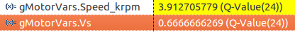
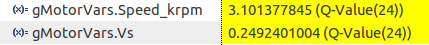
How do I add overmodulation to lab11?  The lab notes say it is the same as lab 10a, but lab10a also uses the CTRL object.  I copied runCurrentIgnore, runCurrentReconstruction, and runSetTrigger from 11a.  I also copied the relevant svgencurrentHandle, etc initializations.  The motor runs, but the results are kind of odd.  In lab10 I can acheive ~3900rpm with modulation set to 0.67 and ~3100rpm with modultion of 0.5.  In lab11, with all my additions commented out and USER_MAX_VS_MAG_PU =0.5 I can still reach 3900rpm, shouldn't it only be 3100?


Is there a reccomended way to add stall detection?  I'm thinking of the case where foriegn objects cause the rotor to lock and the motor needs to be shut down to prevent damage.  I noticed when I lock the shaft, speed estimates of ~1krpm are returned in most cases.  My current techniques is to declare a stall when est. rpm is <1.5k and reference rpm is >2.5krpm for > 1 second.  In the case where ref rpm is <2.5k I declare stall if current is >5A for more than 1 second.  Is there a more elegant way?  This is for a fan application.

The motor/controller will need to be tested with the fan removed, but this will wreak havok when used with the high gains required for the fan, the motor will oscillate and be very noisy.  Is there a way to detect the presence of the fan inertia?  Current on startup maybe?  Any other suggestions for how to solve this problem?


Is there a way to selectively optimize files in the motorware projects?  I noticed by default the debug level is 2, this make actually debugging anything quite a challenge.  If I set optimization to 0 the code is either too large or doesn't run.  I would like to be able to optimize most of the files, but leave the ones I am working on at -o0.

Should Is_A match up with the measured input current?  I had to increase USER_IQ_FULL_SCALE_CURRENT_A to 25 for my motor to reach full power.  When testing at full power Is_A shows >20A, but my power supply shows like 18A.

That's all I have for now.  Thanks in advance for the help.

  • over modulation is already included in proj_lab11a

    why not just use 11a instead of 11?


    "I noticed when I lock the shaft, speed estimates of ~1krpm are returned in most cases."

    You should be seeing speeds close to 0 with no Bemf being generated. This makes me think there is something else wrong with your system. Make sure your compiler is 6.2.4+ and that your motor parameters seem reasonable.

    "Should Is_A match up with the measured input current? "
    No.
  • "why not just use 11a instead of 11?"
    Because I don't need:
    Rs recalculation
    Speed and Id ramps (in fact I want the opposite)
    ACIM support
    Powerwarp
    Rs Online
    Field weakening
    1/VBus compensation
    CPU usage calculation

    If there is some guide on how to remove these features I would use 11a, but I thought it would be easier to add offset calculation (already working) and overmodulation to 11.

    I see 100s of RPM when I stall the motor, ~1000 if I stall at higher power. I have been testing this by having the motor run and grabbing the rotor with a gloved hand, so there is still some wiggle allowed, but this is not unrealistic. My motor parameters:

    #define USER_MOTOR_TYPE MOTOR_Type_Pm
    #define USER_MOTOR_NUM_POLE_PAIRS (7)
    #define USER_MOTOR_Rr (NULL)
    #define USER_MOTOR_Rs (0.0494326)
    #define USER_MOTOR_Ls_d (0.0000127511)
    #define USER_MOTOR_Ls_q (0.0000127511)
    #define USER_MOTOR_RATED_FLUX (0.010631936602294445)
    #define USER_MOTOR_MAGNETIZING_CURRENT (NULL)
    #define USER_MOTOR_RES_EST_CURRENT (3.0)
    #define USER_MOTOR_IND_EST_CURRENT (-3.0)
    #define USER_MOTOR_MAX_CURRENT (20.0)
    #define USER_MOTOR_FLUX_EST_FREQ_Hz (80.0)
    Any others you require? Other things to test? maybe changing some frequencies?

    compiler is version 6.4.2.

    I wish to report back current and voltage to the controlling system. How can I get DC input power?

    Thanks for the help.
  • we tested out lab11 by adding in the SVGENCURRENT and we get same results for 0.5 and 0.666 as with 11a.
    perhaps you made a mistake somewhere?

    your motor parameters look reasonable...this is a hobby type motor?

    "I wish to report back current and voltage to the controlling system. How can I get DC input power?"
    You would need to add hardware bus current measurement to get a reliable input power type calculation. the currents we are measuring in each phase through the low-side shunts include recirculation currents.

    there are quite a few threads about power measurement on the forums you can search. ex:
    e2e.ti.com/.../1598105
  • Chris,

    Thanks for the quick response. I'll test with a virgin set of motorware labs and report back.

    Yes, this is a hobby motor. Any ideas on the problems with est rpm?

    I'll look at the power measurement stuff. I don't need it to be super accurate.
  • Hello Dr. Proton,


    We get asked about the power question a lot.  In fact, we are considering adding a feature in Motorware to do this.

    As Chris pointed out, we are only concerned with MOTOR voltages and currents from a control perspective.  Since we don't measure bus current, we cannot directly calculate bus power.  But we CAN calculate motor input power.  The easiest way to do this is with synchronous frame variables.  Since we are using the amplitude invariant form of the Clarke transform, motor power can be calculated as follows:

    Motor input power =  1.5 * (Vsd * Isd + Vsq * Isq)

    Also, battery power = Motor input power + inverter loss power.

    To determine you inverter losses under different load conditions, you could run some tests.  Use a DC voltmeter and ammeter to measure battery power, and then subtract motor power from the equation above.  The answer should then be your inverter losses.  So you could characterize your inverter losses over different conditions and even build a LUT in code to characterize inverter losses as a function of motor power.  From then on, you could add motor power to your inverter power to get battery power.  If you want, you could even use your calculated bus power and divide it by your measurement of battery voltage to get bus current.

    Please keep in mind that InstaSPIN-FOC is not guaranteed to work at zero speed, or a stall condition.  Usually it works for just a little while before giving up, but since your inductances are so low, I doubt if you can use it at all for velocity information when it is stalled, since the angle lock will be lost.  Let me think about this a little more to see what options you might have...

    Regards,

    Dave


  • I just redid the tests with unedited motorware 115 labs.  My results:

    Lab 10a - USER_MAX_VS_MAG = 2/3

    Overmodulation=0.67, ~3850rpm

    Overmodulation=0.5, ~3130rpm

    Lab 11 - remember, not modified with overmodulation
    USER_MAX_VS_MAG =2/3, ~3930rpm

    USER_MAX_VS_MAG=0.5, ~3890rpm

    Lab 11a

    USER_MAX_VS_MAG=2/3, ~4000rpm

    USER_MAX_VS_MAG=0.5, ~3980rpm

    The only changes I made were to add my motor to user.h, and change the speed PI gains to 0.15 and 0.001 (same gains used for all labs).  Why are labs 11 and 11a so close, but lab 10 so different?  In this case the motor does not have a load connected.  I don't really care about the slight variations in upper RPM, I want to know why I got the 3100 rpm result.


    The motor I am testing with in this case is:


    #define USER_MOTOR_TYPE                 MOTOR_Type_Pm
    #define USER_MOTOR_NUM_POLE_PAIRS       (12)
    #define USER_MOTOR_Rr                   (NULL)
    #define USER_MOTOR_Rs                   (0.412260681390762)
    #define USER_MOTOR_Ls_d                 (.00021836803352925926)
    #define USER_MOTOR_Ls_q                 (.00021836803352925926)
    #define USER_MOTOR_RATED_FLUX           (0.0094)
    #define USER_MOTOR_MAGNETIZING_CURRENT  (NULL)
    #define USER_MOTOR_RES_EST_CURRENT      (0.5)
    #define USER_MOTOR_IND_EST_CURRENT      (-0.5)
    #define USER_MOTOR_MAX_CURRENT          (4.0)
    #define USER_MOTOR_FLUX_EST_FREQ_Hz     (80.0)

    I don't need very accurate power measurements, just accurate enough to tell if something has gone horribly wrong.  I think ignoring inverter loss will be just fine for me.

    I don't really need velocity information when stalled, I just need to know that it is stalled.  My technique seems to work okay, but I can't help but feel that there is a better way.

    P.S.

    Dave, your videos on motor control I found on youtube are excellent.  The concepts are very well explained and easy to understand, thank you for creating them.
    Would you be kind enough to send me a link to your blog post about different integrator clamping techniques?

  • Dr. Proton,

    I am glad that my videos were helpful.  The best way to get to all of my blogs on PI controllers is to just google "teaching your pi controller to behave".  Part 7 in particular deals with integrator clamping.


    I agree that you don't need an accurate estimation of the velocity signal to determine whether you have stalled or not.  My concern however is that under a stalled condition, if angle lock is lost, we cannot guarantee anything about the velocity signal.  It could report 0 rpm, 1k rpm, or even 10k rpm.  In fact, I am surprised that it holds steady to a constant value when you stall.  Without understanding how that is happening, I can't guarantee that it will always work like that.

    I'm still thinking about the problem of stall detection.  I have an idea, but I want to bounce it off the other guys on our motor control team.  Stand by...

    Thanks,

    Dave


  • Dave,

    I do not get a steady constant value. I get noisy values averaging around 1krpm.

    I also have the same concern. One thing I noticed was as I allow more current during a stall (by adjusting my bench supply) the rpm estimate seems to get higher. At 20A (the limit of my bench supply) I was getting noisy readings around 1krpm. I'm worried when I hook up a battery things will be really bad. I was hoping TIDA-00643 would touch on stall detection, but it did not.

    Any feedback on the overmodulation issue?
  • I checked with the other individuals on our motor control team, and unfortunately we don't have a recommended solution for stall detection.  The problem is that when the speed is zero, we cannot say anything about the accuracy of the flux angle estimate.  And since the speed estimate is related to the angle estimate, we also cannot say anything about its accuracy.  If the speed were ramping down, I would simply suggest that you monitor speed, and if it drops below a value where you know the angle guess is still good, you simply turn off the motor.  But in a stall (which could be caused by an immediate stop of the propeller), you may not have enough time to do this.

    Perhaps you could monitor the speed variable at every sample point, and if for any reason you see an unexpected change in its value beyond a certain threshold, you declare a stall condition and shut it down.  I think this would work because whether the speed estimate is accurate or inaccurate when you stall, the chances that it will remain the same value as before the stall are very remote.

    Regards,

    Dave


  • Is there any way to know if the estimated BEMF is 0? I seem to recall you making mention of a "FEAST" observer in one of the videos.

    Your suggestion is simple enough to test. I'll give it a try. Only problem is that it won't catch a slow stall condition.

    How has stall detection never been an issue in the past?

    Any word on the overmodulation issue?
  • I repeated the overmodulation tests with a load and got similar results. Lab 10 with modulation=0.5 got ~4100rpm, all other tests were around 4900rpm
  • Hi DrProton,

    Sorry for my tardy response.

    Knowing if the BEMF is zero is at the core of the problem.  Even if you brought out the back-EMF signals from the FAST observer, you can't trust that the signals will be correct if the speed is below FAST's ability to track them.

    I will be interested in hearing what you find out from my suggestion.  I think you could still detect a slow stall condition if you also compare the speed value to the commanded speed.  If current is high while the actual speed continues to depart from the commanded speed, that should also indicate a slow stall.

    I will need to check with the author of the lab to see how overmodulation could be added.

    -Dave


  • Dave,

    I'll be trying this shortly. I also had the idea to monitor the Id current. If the angle is chaotic the Id current would likely be chaotic as well?

    I can add overmodulation to the labs just fine. My concern is why does it have such a large effect in lab 10, and such a little effect in labs 11 and 11a. Futhermore why does lab 11, without overmodulation support, reach approximately the same speed as lab 10 with modulation=0.67?
  • Yes, once you have lost angle lock, the current will probably go nuts too.  I suspect that when angle lock is lost, all of the controlled parameters (speed and currents) will no longer equal their commanded values.  I hope this can be used to give an indication that something is wrong.

    With MotorWare15, we changed our voltage scaling by a factor of 2.  This may be what you are seeing.  Also, have you tried lab 11b?  This has a new and improved overmodulation algorithm which allows you to go all the way up to 4/3 overmodulation without loss of control.  At mod index of 1.333, the waveforms are no longer sinewaves, but trapezoidal.  The space vector plot is no longer a circle, but a hexagon.

    -Dave


  • Dave,

    My idea is to low pass filter Id and apply some criteria to this. Not sure if it will work, but it sounds reasonable.

    I am aware of the change between motorware 115 and 114.

    Do you mean lab11a? 11b is related to vibration compensation. I have tried lab 11a. Is there a scaling difference between lab 10 and lab 11/11a? Why does lab 11 with USER_MAX_VS_MAG_PU =0.67 achieve the same RPM as lab10 with gMotorVars.Overmodulation=0.67? And why does lab 11 with USER_MAX_VS_MAG_PU=0.5 reach nearly the same RPM as with USER_MAX_VS_MAG_PU=0.67, but lab 10 with gMotorVars.Overmodulation=0.5 achieve ~20% lower RPM?
  • Hi,

    I tested lab 10a and compared vs. lab 11a, and also made modifications to lab 11 so that it does overmodulation. The results are the same for all three. Here are my test results:

    Modified lab 11:

    Lab 10a:

    There is a slightly higher speed reached with lab 10a (0.5%), which is negligible in my opinion. Not sure where the 20% came from on your tests. One thing to note though is that in labs 11 and 11a, there is only one parameter to change in user.h to limit the Vs vector (USER_MAX_VS_MAG_PU), but in lab 10a, you need to actually change a global variable (gMotorVars.OverModulation).

    -Jorge

  • I agree the slightly higher speed is probably negligible. I have been changing the parameters you mentioned. Did you also try an unmodified lab11 to see what the max speed was?
  • If I use the original lab 11, and if I limit the output vector Vs to 0.5, then I get this:

    Although the current is noisy, and the speed varies quite a bit. Then if I change the limit to 2.0/3.0 and I try to go beyond 5000 RPM, the current controller becomes unstable, which causes the speed controller to go unstable, and generates an overvoltage, dropping the JTAG communication and resetting the device. This is expected though, since the current samples are not correct due to the narrow sampling window available, that's why the overmodulation changes are needed.

    -Jorge

  • What electrical RPM are you running at? What motor are you using?
  • I am running the Anaheim motor. It's a four pole pair motor, so Hz = RPM / 60 * 4. These are the motor parameters:
    #elif (USER_MOTOR == Anaheim_BLY172S)
    #define USER_MOTOR_TYPE MOTOR_Type_Pm
    #define USER_MOTOR_NUM_POLE_PAIRS (4)
    #define USER_MOTOR_Rr (NULL)
    #define USER_MOTOR_Rs (0.3968007)
    #define USER_MOTOR_Ls_d (0.0006708066)
    #define USER_MOTOR_Ls_q (0.0006708066)
    #define USER_MOTOR_RATED_FLUX (0.03433958)
    #define USER_MOTOR_MAGNETIZING_CURRENT (NULL)
    #define USER_MOTOR_RES_EST_CURRENT (1.0)
    #define USER_MOTOR_IND_EST_CURRENT (-1.0)
    #define USER_MOTOR_MAX_CURRENT (5.0)
    #define USER_MOTOR_FLUX_EST_FREQ_Hz (20.0)
  • Is it possible that something about my motor is causing this behaviour? I'll see if I can find a more "industrial" motor and test with it.
  • Hi Dr. Proton,

    FAST is the observer that is used by InstaSPIN (Flux, Angle, Speed, Torque).  And it works great above a minimum speed and speed reversal through zero speed.  Stall conditions can be identified with the stall defined in your system's minimum speed.  Please take a look at the InstaSPIN User's Guide for a comprehensive overview:  .  

    Below is a snippet form the UG:

    Jeff

  • Can you point me to a particular section? section 14.1.1.4 talks about tuning the controller to prevent stall. This does nothing to prevent the case where a foreign object locks the motor instantly. In this case it has been my experience that FAST produces estimates around 1000rpm. Dave was saying that even this cannot be relied upon.
  • Wouldn't the current measurement show you the motor being locked? Also the speed estimate will go below your threshold for stall detection.
  • Not sure what is causing the difference. Could you please send screen captures of the values of Vs and Speed just like the ones I sent out?

    Also, you might want to set the PI gains on the speed controller to the same values for 10a and 11 or 11a.

    I think the user's guide post was an oversight. Sorry about that.

    -Jorge

  • As it is right now the I have the max current set only a little bit greater than the maximum current output under load. I think I can bump up the max current to be well in excess of the maximum continuous current, and hopefully not blow fuses. Thanks for the suggestion.
  • Will do. I did set the speed PI gains the same for all labs. I'll double check current PI though. hopefully I can get this done today, but it will probably be tomorrow.
  • I ran the tests again.


    Lab 11 - unmodified, I only changed speed PID values

    Lab 10 - again unmodified

    I confirmed the curent PI values are the same for both labs.  One odd thing I noticed is that in lab 11 at ~3100 rpm I get this:

  • That is interesting. Could you capture the same for lab 11a? Are you using MW15?

    -Jorge

  • Yes I am using MW15. I'll test lab11a as well, but it has been my experience that it is almost identical to lab 11.
  • Results with lab11a

    Hope this helps.  The motor in this case has 12 pole pairs, could there be some issue with high rpm?

  • I hate to bump my own thread, but is there any update on this?
  • Could you please run at lower speeds, so it doesn't go into saturation, to see if it is the same scaling? So for example, run labs 11a and 10a, at 1000 RPM and 2000 RPM, and capture both speeds and Vs for both labs. They should use a similar Vs for the same speed.

    -Jorge

  • Seems pretty consistent.  My results:

    lab10a:

    lab 11:

    lab 11a

    Where do I go from here?

  • your results for lab10 are using twice as much voltage as the results in labs11

    there is scaling factor of 2 off in something you've done

    can you verify the USER_MOTOR_NUM_POLE_PAIRS being used for each active motor in user.h?

  • These should be unaltered labs from MW15. I only changed the speed KP and KI in labs 11 and 11a. All labs build from the same source, same user.h file and run use the same motor. I'll be happy to share my code if you like.

    I get very close to the same max RPM with all labs set to 0.67, so I don't think there is an issue with the pole count. I'll do the check you suggest though. I'll also download MW15 again tonight, copy my motor and gains in and try again. It's possible I fumbled a key somewhere in the code and simply didn't notice.
  • Lab 10a:

    Lab 11:

    Lab 11a:

    Same results with all three labs. This is using a fresh install of MW15, and an DRV8312 kit, with 28069F and an Anaheim motor. I don't know what is the difference with your system, but I can't replicate your results. Could you try a fresh MW15 install with a standard TI kit?

    Thanks,

    -Jorge

  • I downloaded a fresh copy of motorware straight from the TI site. I got the same results. I tried with another more "industrial" motor, a tecmotion FL42BLS01-001. My results are inline with previous motor:

    10a
    1krpm VS=0.087
    2krpm VS=0.175
    7.08krpm VS=0.66
    5.78krpm VS=0.5

    11
    1krpm VS=0.044
    2krpm VS=0.09
    7.3krpm VS=0.666
    7.25krpm VS=0.5

    11a
    1krpm VS=0.44
    2krpm VS=0.089
    7.4krpm VS=0.66
    7.34krpm VS=0.5

    Motor parameters:
    #elif (USER_MOTOR == TECMOTION_FL42)
    #define USER_MOTOR_TYPE MOTOR_Type_Pm
    #define USER_MOTOR_NUM_POLE_PAIRS (4)
    #define USER_MOTOR_Rr (NULL)
    #define USER_MOTOR_Rs (0.20061026513576508)
    #define USER_MOTOR_Ls_d (0.0002868412993848324)
    #define USER_MOTOR_Ls_q (0.0002868412993848324)
    #define USER_MOTOR_RATED_FLUX (0.015188997611403465)
    #define USER_MOTOR_MAGNETIZING_CURRENT (NULL)
    #define USER_MOTOR_RES_EST_CURRENT (1.0)
    #define USER_MOTOR_IND_EST_CURRENT (-1.0)
    #define USER_MOTOR_MAX_CURRENT (5.0)
    #define USER_MOTOR_FLUX_EST_FREQ_Hz (20.0)

    In desperation I removed all other motorware projects from my workspace, but this had no effect. Is there any chance my workspace could be "polluted" somehow? One odd thing I noticed is that in labs 11/11a I don't get high VS until VERY near full speed. Running at 5.8krpm, VS=~0.25 in both cases.

    I am using a LAUNCHXL-F28027F with a boostxl-drv8301. I have seen similar results with the 8305 as well. Can you test on this platform? If you can't replicate the results can you compile with my motor parameters and send me some .out files?

    I also cut JP5,JP7,JP8, and JP10 on my board.

    PS. Thank whomever is responsible for fixing all the case errors in the project paths, this was a big headache on linux.
  • I tried with LAUNCHXL-F28027F and BOOSTXL-DRV8305 and Anaheim/Telco NEMA 17 motor with 18V bus.

    10a
    1 KRPM Vs = 0.14
    2 KRPM Vs = 0.27
    4.7 KRPM Vs = 0.67

    11
    1 KRPM Vs = 0.14
    2 KRPM Vs = 0.27
    3.7 KRPM Vs = 0.5 (saturated to limit in user.h)


    I am not able to reproduce your results.

    Are you sure that you are using the same user.h for both projects?
  • I'll double check, but I can't see how I could have multiple user.h files.

    Could you build the projects for the LAUNCHXL-F28027F and BOOSTXL-DRV8301 combo with my motor parameters and send me the .out files?
  • rename to .zip

    this has the user.h and all three .out files
  • Thank you. I'll test it tonight.
  • Just finished testing this. With your .out I got the following results:

    10a
    1krpm VS=.090
    2krpm VS=.175
    7.127krpm VS=0.67
    5.78krpm VS=0.5

    11
    1krpm VS=0.045
    2krpm VS=0.090
    7.27krpm VS=0.5

    11a
    1krpm VS=0.045
    2krpm VS=0.09
    7.35krpm VS=0.5

    So, still the same problem. I tried another lower frequency motor, still the same problem. Then I tried running the motor at higher voltage, my tests thus far have been at 12v. Some more numbers:

    10a @ 20v
    1krpm VS=0.050
    2krpm VS=0.10
    12.2.krpm VS=0.67
    9.93krpm VS=0.5

    11 @ 20v
    1krpm VS=0.045
    2krpm VS=0.087
    12.08krpm VS=0.67
    11.44krpm VS=0.5

    11a@20v
    1krpm VS=0.045
    2krpm VS=0.087
    11.7krpm VS=0.5
    12.00krpm VS=0.54 (but was set to MAX=0.67)
    12.23krpm VS=0.67 (USER_IQ_FULL_SCALE_FREQ_Hz now increased to 1000)

    So it seems that VS is not scaling with voltage for lab 11, but is for 10a? Does this provide any more clues? Sorry I don't have a 24v supply handy to go to exactly double the voltage.
  • I see what the issue is now. The difference between lab 11 and lab 10a is how 1/vbus compensation is done. For lab 10a, the compensation is done by scaling the Kp gain of the current controllers, so Vd and Vq will be scaled with 1/Vbus. Lab 11, scales Valpha and Vbeta with Vbus. We made this change since scaling Valpha and Vbeta has better dynamics as opposed to scaling Kp of the current controllers. This is because when scaling Kp in a series implementation of a PI (which is the PI topology we use for the current controllers) that change also passes through an integrator. This might affect the stability of the controllers at high speed, especially if there is Vbus ripple.

    So, to confirm this, please make this change to lab 10a. Open ctrl.h, and in function CTRL_runOnLine_User(), comment out the following lines:

    //     if(CTRL_getFlag_enableDcBusComp(handle))
    //       {
    //         Kp_Id = _IQmpy(Kp_Id,EST_getOneOverDcBus_pu(obj->estHandle));
    //       }

    and

    //     if(CTRL_getFlag_enableDcBusComp(handle))
    //       {
    //         Kp_Iq = _IQmpy(Kp_Iq,EST_getOneOverDcBus_pu(obj->estHandle));
    //       }
    

    Add the following local variables in the same function:

      MATH_vec2 Vab_pu;
      _iq oneOverDcBus;
    

    And add the following code to the same function right before SVGEN_run() function call:

     CTRL_getVab_out_pu(handle,&Vab_pu);
     oneOverDcBus = EST_getOneOverDcBus_pu(obj->estHandle);
     Vab_pu.value[0] = _IQmpy(Vab_pu.value[0],oneOverDcBus);
     Vab_pu.value[1] = _IQmpy(Vab_pu.value[1],oneOverDcBus);
     CTRL_setVab_out_pu(handle,&Vab_pu);

    Once you have done that, try it again with a 12V input as you were doing it before.

    -Jorge

  • Thank you for that. Everything lines up now:

    lab 10a modified
    1krpm VS=0.045
    2krpm VS=0.09
    7.4krpm VS=0.67
    7.34krpm VS=0.5

    11
    1krpm VS=0.45
    2krpm VS=0.087
    7.33krpm VS=0.67
    7.27krpm VS=0.5

    11a
    1krpm VS=0.045
    2krpm VS=0.089
    7.36krpm VS=0.5
    7.43krpm VS=0.67

    So this alternate scheme seems to render overmodulation almost completely unnecessary, is this expected?
  • Overmodulation is still active. However, I would check Valpha and Vbeta instead, to see when it goes into overmodulation. If the peak amplitude of alpha or beta is 0.6667 then it would create the maximum overmodulation creating a trapezoidal voltage on the output.

    We are discussing internally what is the best way to limit the outputs of the PI controllers though, specifically for lab 11, since the output is scaled by 1/Vbus, then the maximum output of the PI needs to be scaled with Vbus to avoid going beyond the limit when scaled by 1/Vbus.

    This will be figured out and fixed on the next revision. Let me know if you have any other questions.

    -Jorge

  • I guess the only questions I have left are:

    Should I base my solution on lab11 or lab 10?

    When will the new version of motorware be out?