This thread has been locked.

If you have a related question, please click the "Ask a related question" button in the top right corner. The newly created question will be automatically linked to this question.

AMC1304M25 Delta Sigma Modulator and TMS320F28377S SDFM

Other Parts Discussed in Thread: TMS320F28377S, CONTROLSUITE

Hi,

I am using Sigma Delta Modulator 1304M25 and related digital filter SDFM from TMS320F28377S to measure the currents/ voltages of inverter in automotive applications.


The TI example that i used for this is controlsuite\...\sdfm_sync_cpu_cpu01 with following settings

SDFM: 1

Input control Mode: Mode0

Comparator: COSR_32, Sinc3

Data Filter channel 1: DOSR_256, Sinc3, Data output 16-Bit, Shift Bits_9

Interrupts Activated: MFIE (modulator clock Fail), AFx (Filter Acknowledge interrupts), Under-Current Threshold ( IEL ), Over-Current Threshold ( IEH )

External Filter Reset (FILRES): Disabled, Filter Data Rate = Modulator Data Rate (10Mhz) / DOSR (256) = 39,1KSPS and Latency = SINC3 / Filter Data Rate = 76,8uS

Clock Frequency: 10Mhz, Same clock signal feeds SDFM and SD-Modulator

Modulator Data update on each CLK falling edge.

SDFM data strobing at each CLK rising edge.

SDFM ISR Routine reads data on each Acknowledge Interrupt.

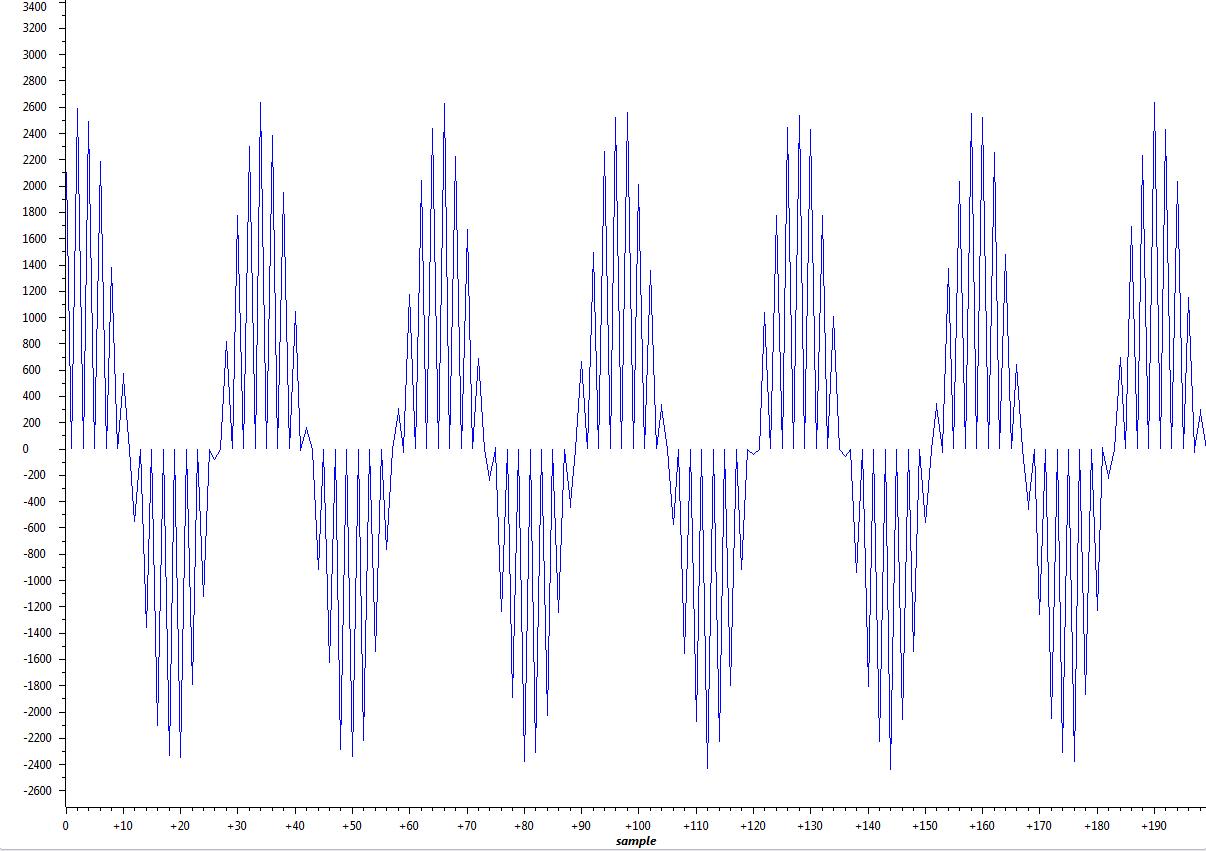
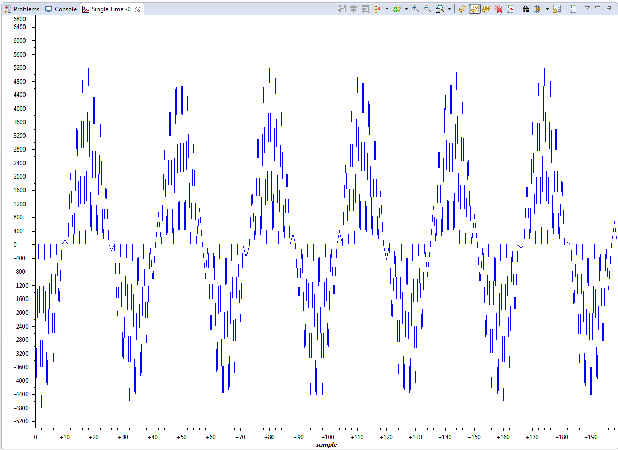
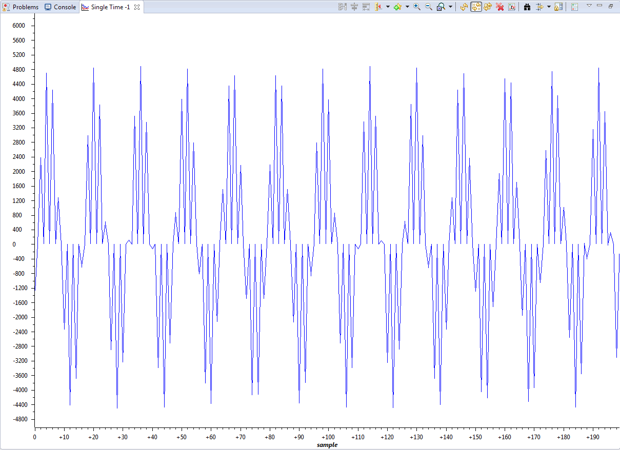
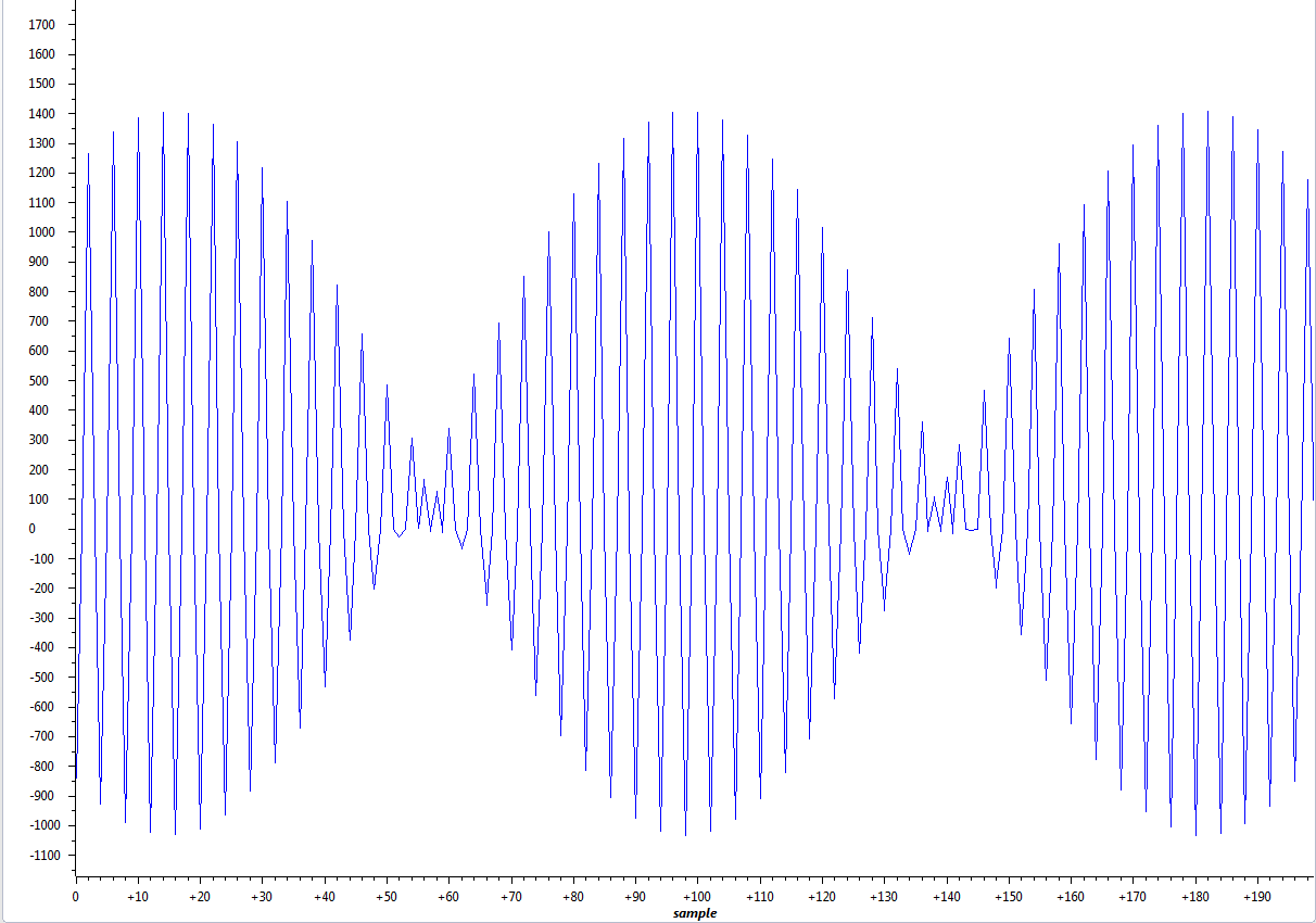
1) I want to know the permitted frequency range of analog input AINP, AINN to delta sigma modulator? I am getting a nice Sine wave at Filter output with analog input having frequency 1KHz, but as soon as I increase the analog input signal freuqncy from 1 KHz to 5 KHz or 10KHz, the results get worse and I can't see a sine wave anymore. I tried increasing Clock frequency to 20MHz but it didn't help. Could someone please tell me where do I stilll lack?

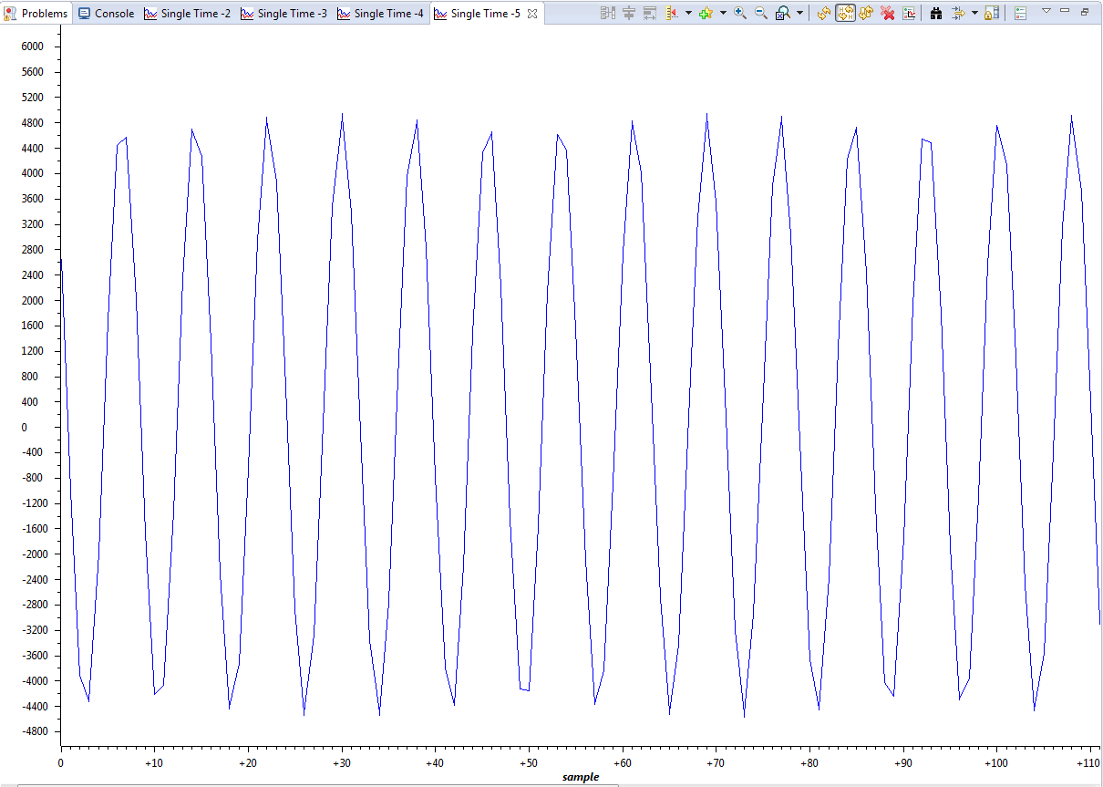
Below both of outputs at input frequency of 1KHz and 10KHz

a) Analog signal: Vpp 100mV, 1 KHz, CLK 10 MHz

b) Analog Signal: 100mV Vpp, Input Frequency 10KHz, Clock 20MHz

Thank you for your help in advance.

Best Regards,

Inam

  • As far as I got to know so far, i need to increase my Filter data rate somehow.

    Filter Data Rate = Modulator Data Rate / DOSR

    If I decrease the DOSR from 256 to 64 or 32, I get a nice sine wave again but of course, resolution of the filter will not be that high as before.

    Clock 10 MHz, DOSR 32, Analog Signal : 10KHz 100mV Vpp

    I would be happy if someone can confirm if this is was the right solution.

    Best Regards,

    Inam

  • Inam,


    Why does your output waveform look amplitude modulated? Can you send a snapshot of SDFM settings in memory window?


    Regards,

    Manoj

  • Hi Manhoj,

    Did you mean the waveform that I put under b) Analog Signal: 100mV Vpp, Input Frequency 10KHz, Clock 20MHz in my first Post?

    That is the problem that I get when I feed an analog input signal of 10Khz with SDFM settings I mentioned before in my Post.

    When I change my data filter OSR from 256 to 32 with 10MHz CLK, then I get the waveform that I uploaded in my last post.

    My question is

    a) Is it a right solution to decrase DOSR when input signal has a high frequency of 10KHz?

    I tried out taking a snap of memory browser for SDFM1, as I am new at Code Composer Studio, I am not sure if I could get what you meant

    SDFM settings snap in memory browser

    Regards,

    Inam

  • Inam,

    My guess is we are looking into a aliasing problem. When you reduce your DOSR, you are increasing the data filter sample rate and hence you are able to reconstruct the signal properly. Why do you want to provide 10KHz signal to modulator? (is there a specific reason?)

    What are your application requirements?

    Pg 19 AMC1304 datasheet, shows that they have tested with 5KHz signal (with 20MHz CLKIN and OSR = 256). Did you already try that?

    Regards,
    Manoj
  • Hi Manhoj,

    Do you think if input signal is 10KHz or 20KHz, Modulator Clock frequency 20MHz, SDFM >Mode 0 so Modulator Sample Rate 20MHz
    can it cause aliasing problem with low DOSR such as 32? Data Rate of filter is hence 625KSPS.

    I need to use AMC1304 for inverter current and voltage measurements for automotive applications. For current measurement I don't see any aliasing problem but I am afraid that voltage signals (phase-phase) must be having higher frequency around 10Khz and must be having alot of switching noise over them.

    I tried an input signal of 5KHz as in AMC1304 datasheet but the filter output signal in time domain doesn't seem that good. Therefore, I had to reduce DOSR.

    Regards,
    Inam
  • Inam,

    With 5KHz, you should get a clean sine wave in time domain. Something is wrong in your code setup / hardware setup. Please check.

    Regards,

    Manoj

  • Dear Manhoj,

    I get this Sine with 5KHz input signal frequency 100mVpp with maximum resolution of filter (OSR_256, Sinc3).

    When I increase input signal frequency to 10KHz, I have only 2-3 samples in one sine half with same filter settings and clock frequency of 20MHz

    Regards,

    Inam

  • Hi Manhoj,

    You are right ! with 20MHz Clock, I am able to get clean sine wave with 5KHz input signal frequency.

    But because my inverter switching frequency is 10KHz, I wanted to test it with 10KHz input signal. In that case, the output sine wave is not clean. A snapshot from input signal with 10KHz frequency:

    Is there anyway to solve this problem without changing the output data rate of filter?

    Inam

  • Inam,

    My sine wave reproduced looks some thing like this. Why does your sine wave look different? In your graph it looks as if every few samples goes to 0.

    The sinewave attached is just an example. I didn't sample 10 KHz as you.

    Regards,

    Manoj

  • Sorry missed attachment in my earlier post....

  • Hi Manhoj,

    Thanks alot for drawing my attention to this.

    I had some problem with calculating two's complement in my interrupt routine. I am able to get the similar signal now as you

    When I sample at input frequerncy of 10Khz

    Regards,

    Inam

  • Inam,

    Please close the post, if your query has been answered.

    Regards,

    Manoj