


Hello there
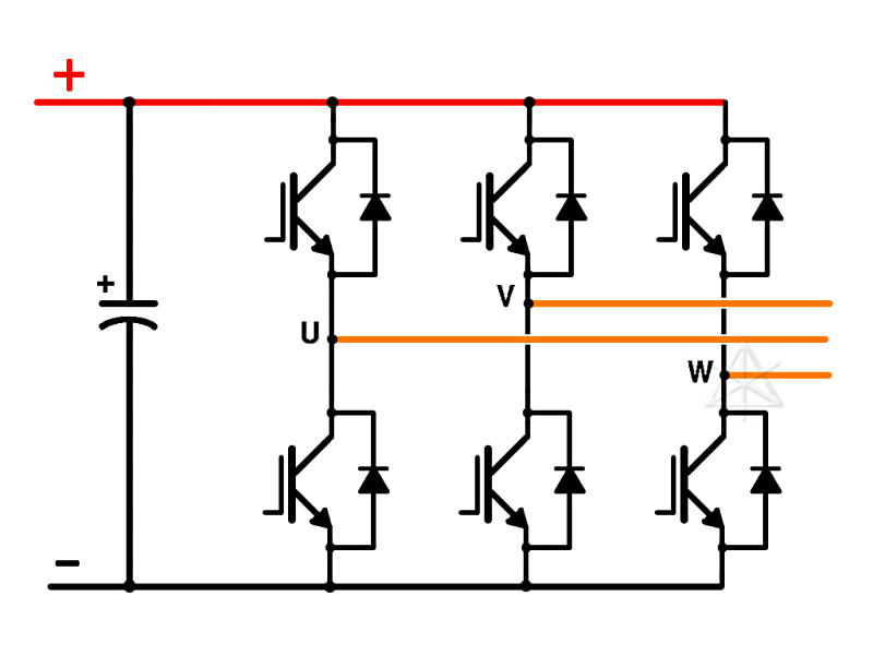
I am intending to use this DSP to generate PWM signals for a conventional 3-phase, 6 switch DC-AC inverter, like the one shown below:
However, I am not sure how to go about this.
I did something similar with the TIVA C Series microcontroller a year ago. I used the general purpose timers to generate interrupts and within the corresponding interrupt service routine I would then toggle the GPIOs and load the next desired pulse width into the timer and set it off again, thus generating PWM signals for all 6 switches. This is the way I originally intended to implement it with the TMS320 as well. However, my supervisor said it is best to use the PWM peripherals to generate them. I am aware that the PWM modules allow for programmable dead-time into the PWM output, which is a big plus but I am a little confused as to how I can program them to do exactly what i want.
My aims are to generate a set of 3-phase PWM signals (with complementary signals) to control each phase 'leg' of the inverter. But the duty cycles should vary sinusoidally with time at a lower frequency, with each PWM duty cycle being be displaced by 120 degrees phase difference with respect to the other two sets. The following picture illustrates what I mean:

With signals Eu, Ev and Ew controlling each phase leg. It is the sinusoidally varying duty cycle I am not sure how to implement. And how to keep the phase relationships between the 3 sets of duty cycles constant.
I was thinking about using a general purpose timer to generate interrupts in order to periodically update the duty cycles but I am wondering if there is a better way.
Thanks for taking the time to read.

