This thread has been locked.

If you have a related question, please click the "Ask a related question" button in the top right corner. The newly created question will be automatically linked to this question.

DRV8301-69M-KIT: DRV8301-69M-KIT: Running 2 SPI slaves HARDWARE problem

Part Number: DRV8301-69M-KIT
Other Parts Discussed in Thread: MOTORWARE, ISO7241A, DRV8301, TMDSCNCD28069MISO

I have another thread on the software part of this:
e2e.ti.com/.../2216265
"DRV8301-69M-KIT: Running 2 SPI slaves in Motorware labs SPI implementation"

...but I think there is a hardware related problem too

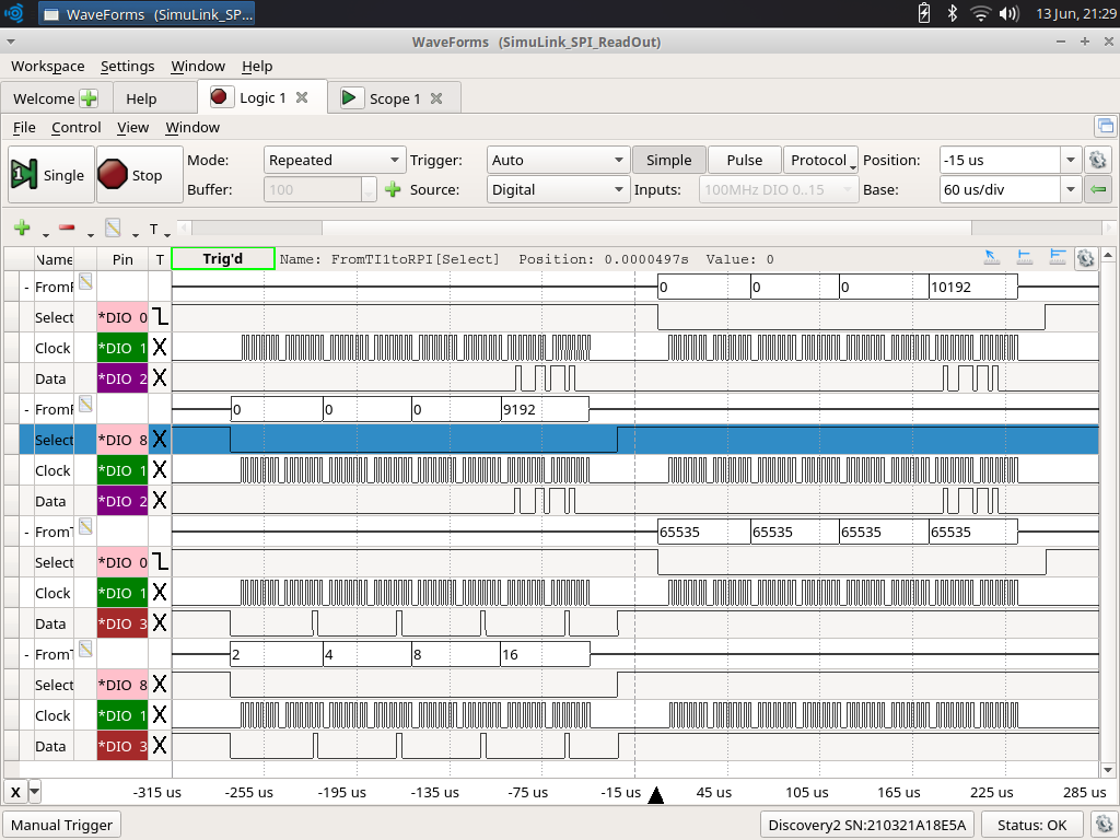
If you want to connect 2 (C2000) SPI slave devices to one master, you need to put the inactive SOMI pin in high impedance mode.
However, the DRV8301-69M-KIT uses a ISO7241A digital isolator. As each of the pins has a fixed direction, I wonder if the IND-OUTD channel can be switched to a high impedance input...

I think using 2 DRV8301-69M-KIT slaves is not possible from a hardware perspective...

I checked for SPI-A SOMI, and I can use 3 GPIO, 3, 17 and 55.

GPIO-3 goes to DRV8301 as PWM-BL, GPIO-17 goes to the digital isolator and can not be intercepted and GPIO-55:
- is connected on the controlcard DIMM100 (F2806XISOCONTROLCARDR0_TMDSCNCD28069MISO.3SCH.pdf)
- is not connected on the driver board DIMM100

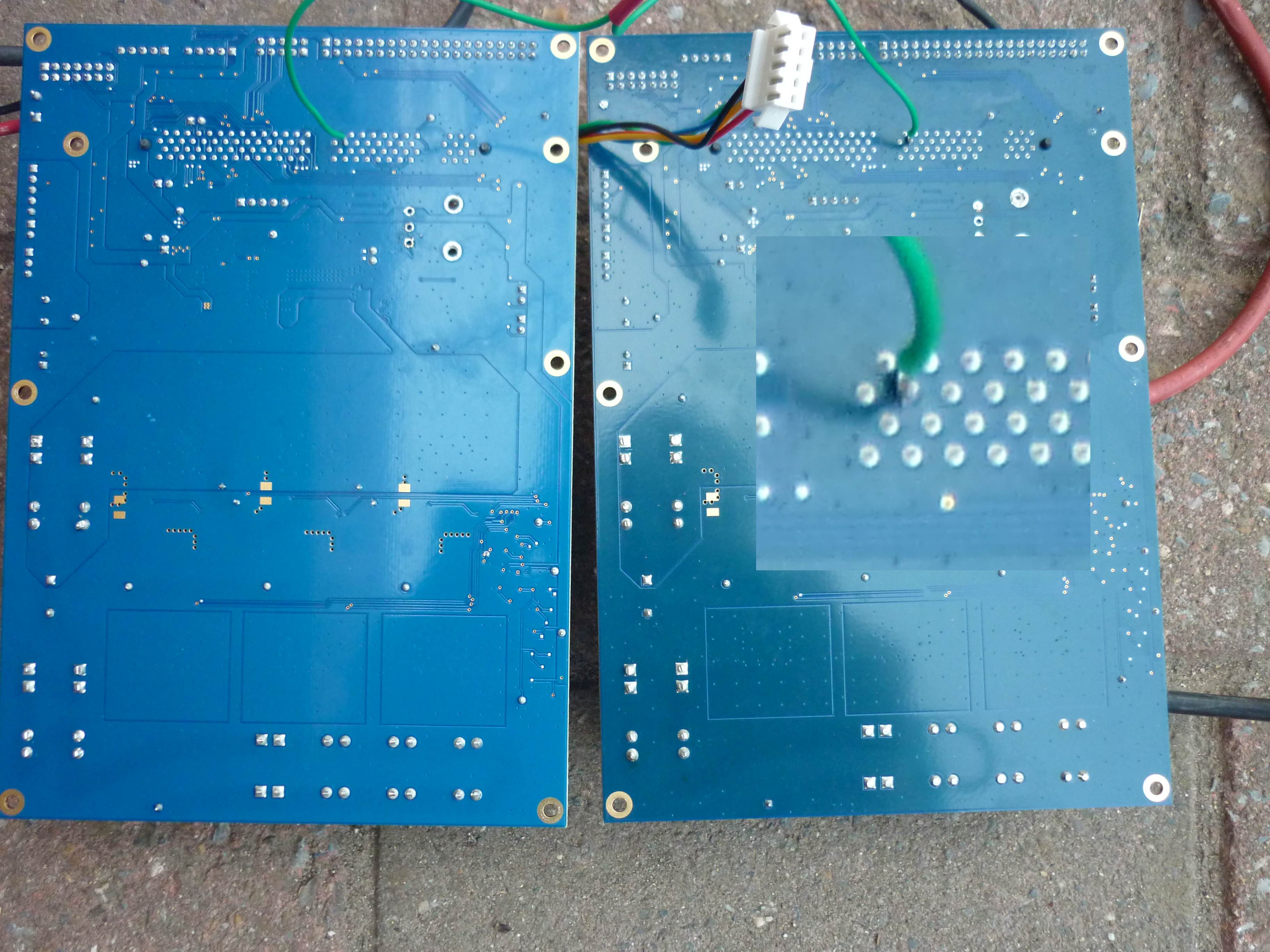
So I plan to solder a small wire to the pin70 of the DIMM100 to make GPIO-55 accessible and to have direct access to SPI-A SOMI to be able to set in high impedance mode.
I will keep you infomed of my progress. I hope I don't blow my board...

My question : can somebody confirm that I can not put the ISO7241A digital isolator output pin in a high impedance state ?

Best regards,
Tomas

  • From the other thread:

    "Mark Labbato wrote the following post at Jun 13, 2017 7:44 PM:

    Tomas,

    The ISO7241A does have an EN pin that can be driven LOW to force the output to high impedance, but there is no input channel switch for the same. Can you share an image of the noise pulses caused by SPICLK switching? It would be good to see both SOMI and SPICLK on the same plot.

    "

    OK, thank you for the clarification. Unfortunately, this enable pin is directly connected to VCCI_3.3V (from DRV8301_Schematic.pdf). Input (clock, select, SIMO) is not a problem as this is driven from the master, and the slave is only listening on these GPIO's. So probably, I will have to give up the isolation for now, but I can do like that when designing a new PCB.

    I made the screenshots and you can find them in attachment. 4 cases:
    1. RPI_Master_2xC2000_Slave_OnlySlave1SPIConnected > OK
    2. RPI_Master_2xC2000_Slave_OnlySlave2SPIConnected > OK
    3. RPI_Master_2xC2000_Slave_Slave1And2SPIConnected_Slave2_TxDisabled > spikes mainly and rising edge of the clock
    4. RPI_Master_2xC2000_Slave_Slave1And2SPIConnected_Slave1And2_TxEnabled > same but slave 1 still can sometimes recognize the data (it has a slightly shorter wire to the master)

    Next 2 in next reply.

    BR,
    Tomas

  • And other pictures:

    3. RPI_Master_2xC2000_Slave_Slave1And2SPIConnected_Slave2_TxDisabled > spikes mainly and rising edge of the clock
    4. RPI_Master_2xC2000_Slave_Slave1And2SPIConnected_Slave1And2_TxEnabled > same but slave 1 still can sometimes recognize the data (it has a slightly shorter wire to the master)

    BR,
    Tomas

    Displaying RPI_Master_2xC2000_Slave_Slave1And2SPIConnected_Slave2_TxDisabled_CROP.png

    Displaying RPI_Master_2xC2000_Slave_Slave1And2SPIConnected_Slave1And2_TxEnabled_CROP.png

  • Tomas,

    The second set of images did not come through.

    I think that your issue is coming down to the Chip select/ TALK bit syncronization. Can you confirm that regardless of a slave's ability to transmit data properly, both slaves are receiving the data as expected? i.e. if you disconnect or ignore the SOMI signals, the master is transmitting and slaves receiving the proper data?

    -Mark
  • Mark,

    Thank you for your reply.

    Yes, I will continue my efforts (probably for the weekend as I only work halftime on this project) and keep you informed.

    I can see also the second set of pictures with spikes when the 2 slaves are connected in a second post. Strange you can't see them.

    I can confirm that I can see the SIMO signals properly with 1 or both slaves connected. I should have explained the buses in the scope picture in my previous post:
    - post #1 with pictures : SIMO slave 1 - SIMO slave 2 - SOMI slave 1 - SOMI slave 2 (2x)
    - post #2 with pictures : SOMI slave 1 - SOMI slave 2 (2x)

    ADDITIONAL QUESTION:
    wouldn't a hardware solution be more simple/possible (I would love to have that on DRV8301-69M-KIT) : connect the !SPI-STEA (I can't put a line above the font) through a NOT port with the SOMI output ISO7241A digital isolator. Maybe an improvement idea for the DRV8301-69M-KIT.

    BR,
    Tomas

  • Connecting 2 slaves on the DRV8301-69M-KIT is not directly possible.

    What I did was to replace GPIO 17 by GPIO 55:

    //  GPIO_setMode(obj->gpioHandle,GPIO_Number_17,GPIO_17_Mode_SPISOMIA);
    GPIO_setMode(obj->gpioHandle,GPIO_Number_17,GPIO_17_Mode_GeneralPurpose);
    //  GPIO_setMode(obj->gpioHandle,GPIO_Number_55,GPIO_55_Mode_GeneralPurpose);
    GPIO_setMode(obj->gpioHandle,GPIO_Number_55,GPIO_55_Mode_SPISOMIA);

    This GPIO is not used on the DRV8301-69M-KIT driver board but it is available at pin 70 from the  DIMM-100 connector.

    So I soldered as small connection wire to this pin and works for now.

  • Tomas,

    I'm glad that you were able to resolve this. As you see, it is difficult to design a general purpose application kit for all possible configurations. So even though another pin with SPISOMIA is not brought out to the design, it is still available on the board. You did exactly what I would have done in this situation.

    Please do share your final design (if you can) when you are complete. You have showed some great work in using the examples that we provide and manipulating them to suit your needs. This is what we strive to do.

    Regards,
    Mark
  • Tomas,

    To answer your direct message in public, where others can find it useful. The C2000 does not limit you to a specific "set" of pins for the SPI or any peripheral. If one GPIO works better for your application, you can configure the mux to the module that you require. Did this GPIO_setMode() function in your above post work or is this still something that you were struggling with?

    -Mark
  • Mark,

    Sorry for my late reply (dividing time between 50% paid job and 50% private project). Thank you for your encouraging comments too. The TI platform is incredible!!! I am a mechanical engineer (mechatronics but that was 20 years ago, after that only noise and vibration) and I could level up my skill based on:
    - this forum that is properly (!) maintained by TI
    - the motorware libraries
    - the prototype boards with detailed hardware description

    I can confirm the above solution works perfectly fine for me. I had a programming bug (late night working) but after solving that, everything runs as expected. So yes, I could just swap the GPIO in the code. For completeness, see how my 2 slaves communicate perfectly in the scope image.

    Thank you again for your help!
    I hope one day to support an application note when my product will be public ;-).

    BR,
    Tomas