This thread has been locked.

If you have a related question, please click the "Ask a related question" button in the top right corner. The newly created question will be automatically linked to this question.

TMS320F280270: 800VA Pure Sine Wave Inverter Reference Design.

Part Number: TMS320F280270

Hello All,

I have currently breadboarded this design with the following parameters.

Parameters

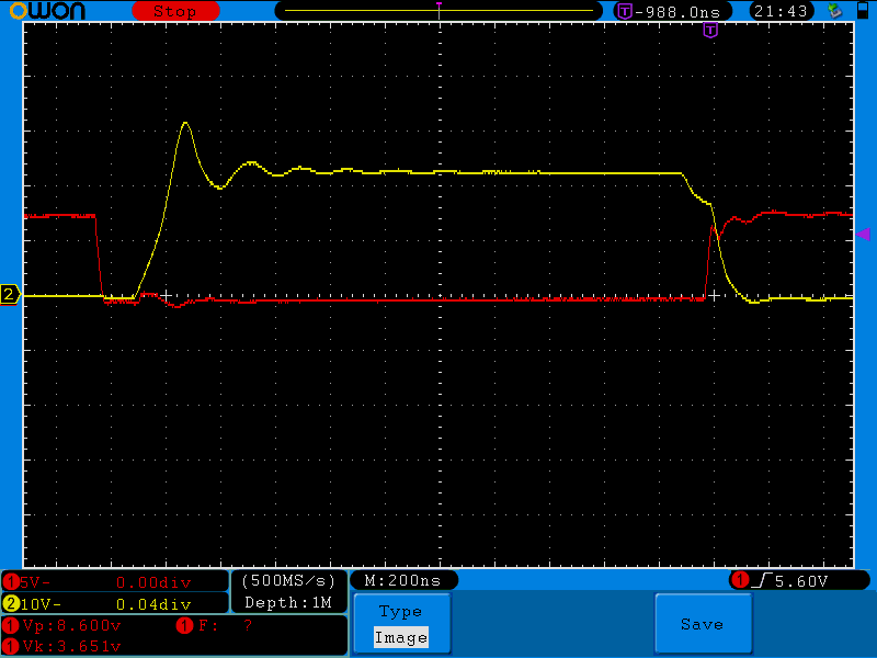
  • Triangle carrier 115kHz
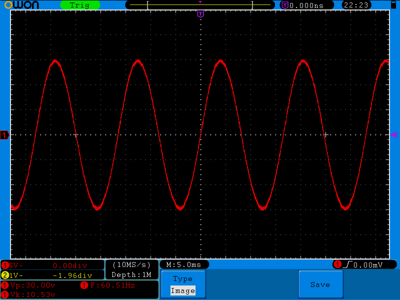
  • Unmodulated signal 60Hz
  • H-Bridge Voltage 30Vdc

I have successfully been able to create the Tri-Level pwm on the output of my H-Bridge circuit and recover the 60Hz sine wave buy LC ( 150uH, 1uF )filtering both output lines. The problem that I am having is that the output sine wave is only 10.5Vac. I think that this is happening because I am using a Tri-Level Pwm and I am only getting half the H-Bridge voltage. If I switch the the Pwm to  Bi-Level will my output sine wave increase to 21Vac.

Regards,

  • Louis,

    Well i'm glad your able to get the correct output shape. You should check if your transistors are turning on fully, you may not have enough drive strength to the gate.

    Just as another sanity check, care you getting any shoot through?


    Regards,
    Cody 

  • Hi Cody,

    It looks like a am getting some shoot through on the AP & AM lines. The same shoot through is happening on the BP & BM lines.

    I am using two Half bridge drivers to power my full H-Bridge circuit and it appears that I have amble drive for the hi side mosfets.

    I did some research on a Tri-Level PWM and it looks like the filter output is (H-Bridge Voltage / 2 ).  Is This Correct?

    My application needs the H-Bridge output not to be half of the H-Bridge supply. Should I still be using a Tri-Level PWM or moved to a Bi-Level PWM?


    I am include a scope shot of the AP & AM gate lines.

  • Hi Everyone,

    I am working on eliminating my shoot  through issue using using resistors and diodes.

    Can anyone help to answer my above prior questions?

    Thanks

    Louis

  • Louis,

    I am not well versed in this application of the PWM, I forwarded this post of a colleague of mine who can hopefully help.

    Regards,
    Cody 

  • Hi Louis,

    You can use the dead-band submodule of the PWM module to provide dead-time between high side and low side switches. You may still want to use an external resistor-diode network to slow down FET turn-on with respect to the turn-off time.

    Hrishi