This thread has been locked.

If you have a related question, please click the "Ask a related question" button in the top right corner. The newly created question will be automatically linked to this question.

TMS320F28332: There is a dip in voltage at ADC Analog input, when CAN Message is received

Part Number: TMS320F28332
Other Parts Discussed in Thread: TMS320F28335,

Hello All,

Background:

I have a proper OPAMP and RC circuit input as suggested for ADC Input signal.

Problem description:

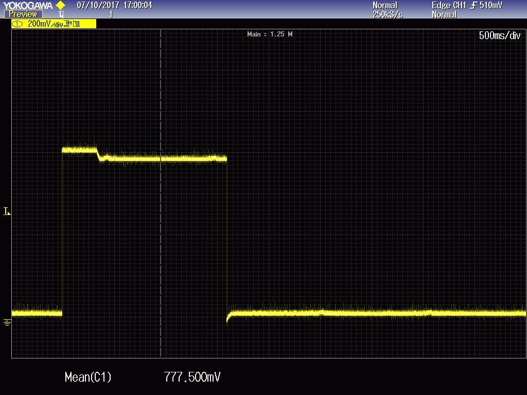
When ever I receive CAN Message (CAN Interrupt), the analog input signal is getting a dip. Initial Analog input is proper but after some time, there will be a dip in the signal. what is causing this Dip. Approximately around 160ms the signal is proper. Later Signal will get a dip.

For example: say the input is 0.8V means, initially it will be around 0.79V and later it ill be around 0.73V.

Testing:
To confirm that it is not due to external signal, above test is done by supplying 0V to analog input, Then it is observed that a dip of around  - 0.3V is seen, when CAN Message is received (ADC Not initialized, No Clock for ADC during this test )


Conclusion:

Hence there is some noise due to the internal circuit of Micro controller. It might be CAN or something other.

Due to this dip, ADC reading is not accurate.

Question:

  What can be the reason for the dip observed? How to Avoid this Dip in input signal?

  • Hi Krishnamurthy,

    What do the voltage levels look like on the CAN pins? is it possible that the can transceiver is outputting a voltage to the device pins that is at least 0.3V less than VSS or more than 0.3V above VDDIO? In this case, significant current may start flowing in/out of the IO pins through the pin clamping diodes, which could affect operation of the system.

    Do the CAN transceiver and the ADC signal conditioning circuits share a power supply? Have you scoped the power supply for the op-amp driving the ADC input to see if it is somehow being affected?
  • Hello Devin

    Thanks for the reply. I done few tests after I posted this.

    I disabled CAN (I mean CAN Init and CAN Interrupt) and then gave command based on timing with out CAN.

    The dip is observed. Hence CAN doesn't have influenced.

    I am using TMS320F28335 not TMS320F28332.

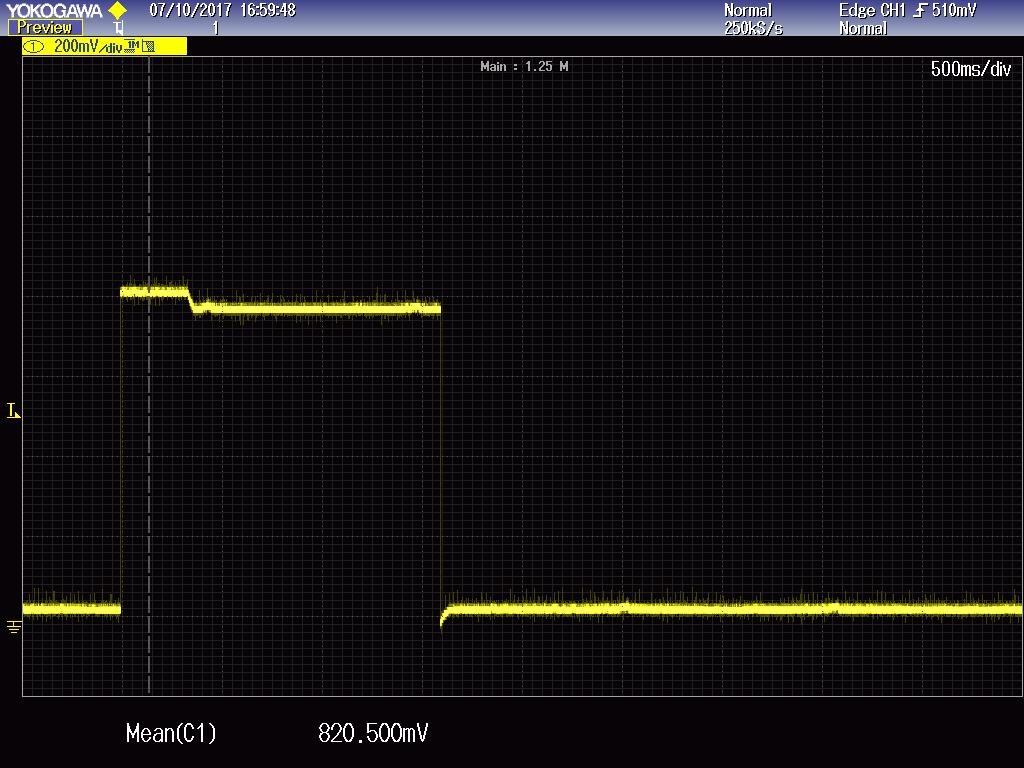
    Am sharing my ADC Configuration, Also the Oscilloscope pic at Analog Input:

    Only 6 ADC lines are being used others are left open. (I will also try pulling them down.)

    I am trying to read only ADCINB7(pin53) Following is my configuration.

    EALLOW;

    SysCtrlRegs.HISPCP.bit.HSPCLK = ADC_MODCLK; // HSPCLK = SYSCLKOUT/ADC_MODCLK

    EDIS;

    InitAdc();

    AdcRegs.ADCTRL1.bit.ACQ_PS =1; //ADC_SHCLK;

    AdcRegs.ADCTRL3.bit.ADCCLKPS = ADC_CKPS;

    AdcRegs.ADCTRL1.bit.SEQ_CASC = 1;        // 1  Cascaded mode

    AdcRegs.ADCMAXCONV.all = 0x0F;

    AdcRegs.ADCCHSELSEQ4.bit.CONV15 = 0xF;

    AdcRegs.ADCTRL1.bit.CONT_RUN = 1; // Setup continuous run

    AdcRegs.ADCTRL2.all = 0x2000;

    The ADC Input at ADCINB7(pin53) is observed as below attached

  • Krishnamurthy,

    It looks like you scope picture covers a very long time period...perhaps 5 seconds with 500ms/div? Would you be able to step through your code or use GPIO profiling to see if there is a particular action that correlates with the voltage dip? I assume that it is the dip that we are concerned about.

    It's strange that the signal settles into a lower steady-state rather than recovering back to the original voltage. Perhaps zooming in can also help to reveal some activity.

    What op-amp and RC values are you using to buffer the ADC signal?

    -Tommy