This thread has been locked.

If you have a related question, please click the "Ask a related question" button in the top right corner. The newly created question will be automatically linked to this question.

TMS320F28027F: PMSM motor identification for low inductance motor using 28027F microcontroller

Part Number: TMS320F28027F
Other Parts Discussed in Thread: DRV8323, MOTORWARE, DRV8305, DRV8301

Good morning,

We're trying to identify the motor inductance and flux for a high speed, low inductance motor (~50krpm, ~32uH) using the 28027F controller and DRV8323 driver, but are finding errors in the inductances identified from testing. Note that we're used motorware successfully in the past for another project a few years ago, so I have some familiarity with the different projects and control methodology.

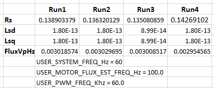
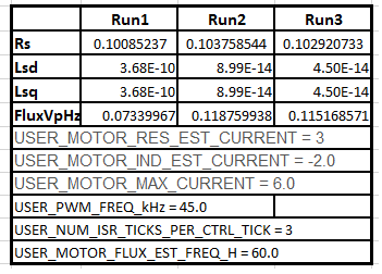
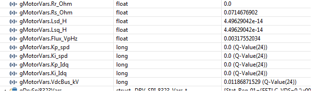
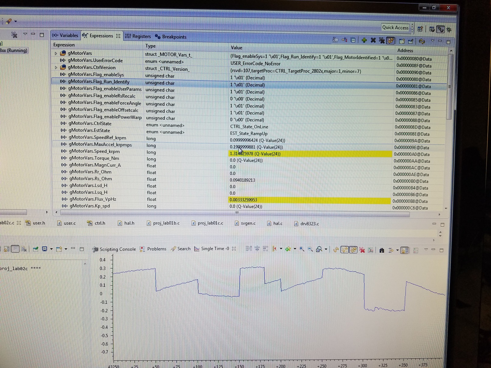
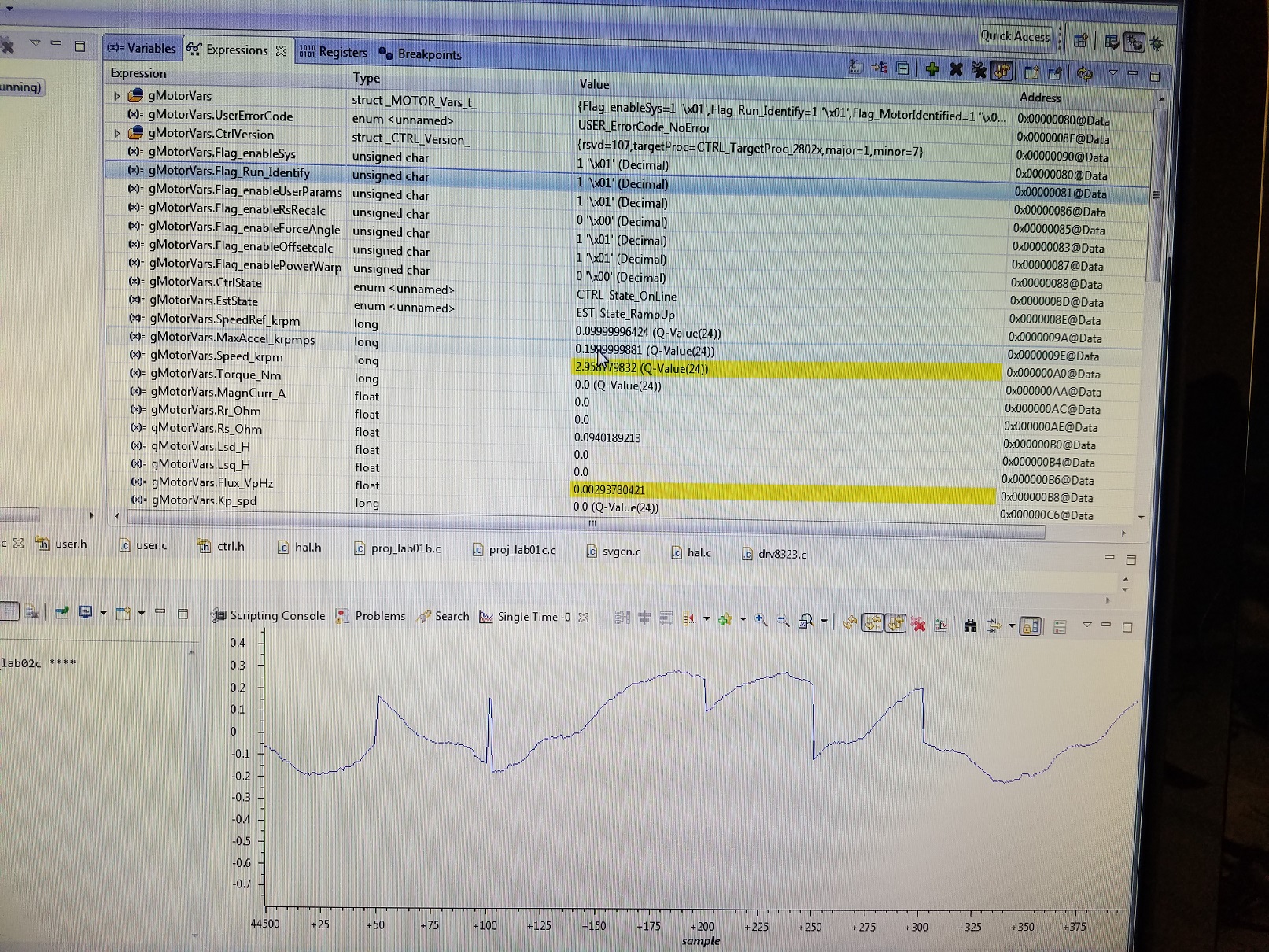
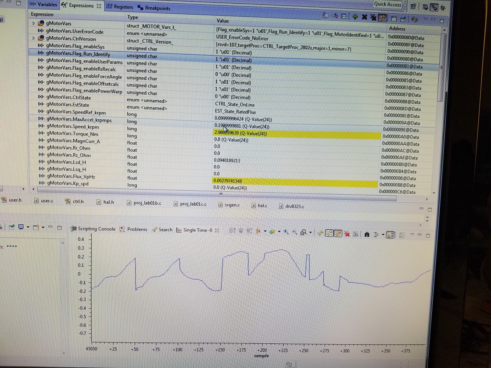
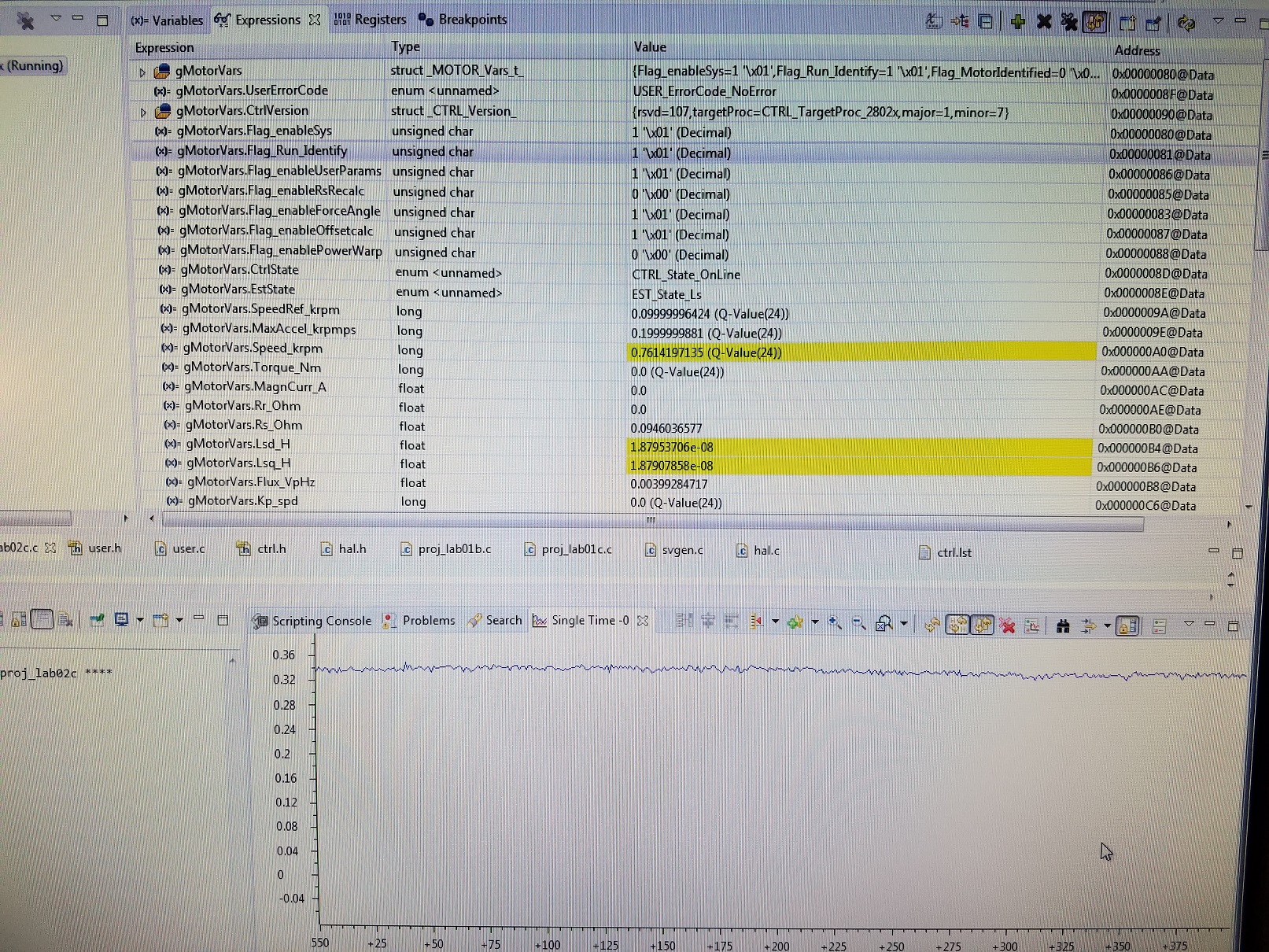
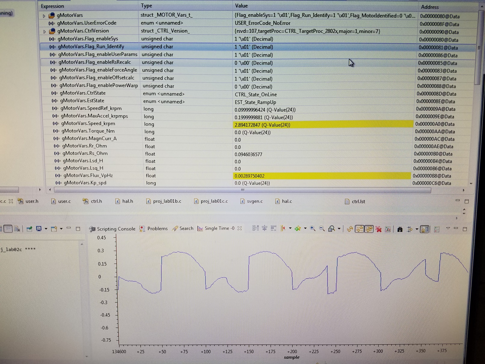
The resistances appear to be in the right order of magnitude, but the lab2c project is identifying motor inductances on the order of 1.e-7 to 1e-13, which I know are too low for my motor. I set the motor max current to 3A in my user.h as a safety, even though the current rating for the motor is much greater than this limit. Could this be influencing the results? I've tried increasing the USER_MOTOR_FLUX_EST_FREQ_Hz  as high as 400Hz but haven't been able to consistently identify the proper inductances. Here are my numbers

Rs

0.055392083

0.056029175

0.070272058

Lsd

3.25E-07

1.35E-07

3.60E-13

Lsq

3.25E-07

1.35E-07

3.60E-13

FluxVpHz

0.0021851

0.00221093

0.002165522

Here are the critical values from my user.h file

#define USER_IQ_FULL_SCALE_FREQ_Hz (1666.7) // Hz =(RPM * Poles) / 120

#define USER_IQ_FULL_SCALE_VOLTAGE_V (14.4)

#define USER_ADC_FULL_SCALE_VOLTAGE_V (22.538)

#define USER_VOLTAGE_SF ((float_t)((USER_ADC_FULL_SCALE_VOLTAGE_V)/(USER_IQ_FULL_SCALE_VOLTAGE_V)))

#define USER_IQ_FULL_SCALE_CURRENT_A (20.625)

#define USER_ADC_FULL_SCALE_CURRENT_A (41.25) //

#define USER_CURRENT_SF ((float_t)((USER_ADC_FULL_SCALE_CURRENT_A)/(USER_IQ_FULL_SCALE_CURRENT_A)))

#define USER_NUM_CURRENT_SENSORS (3) // 3 Preferred setting for best performance across full speed range, allows for 100% duty cycle

#define USER_NUM_VOLTAGE_SENSORS (3) // 3 Required

#define USER_SYSTEM_FREQ_MHz (90.0)

#define USER_PWM_FREQ_kHz (45.0) //30.0 Example, 8.0 - 30.0 KHz typical; 45-80 KHz may be required for very low inductance, high speed motors

#define USER_NUM_PWM_TICKS_PER_ISR_TICK (3)

#define USER_NUM_ISR_TICKS_PER_CTRL_TICK (1) // 2 Example, controller clock rate (CTRL) runs at PWM / 2; ex 30 KHz PWM, 15 KHz control

#define USER_NUM_CTRL_TICKS_PER_CURRENT_TICK (1) // 1 Typical, Forward FOC current controller (Iq/Id/IPARK/SVPWM) runs at same rate as CTRL.

#define USER_NUM_CTRL_TICKS_PER_EST_TICK (1) // 1 Typical, FAST estimator runs at same rate as CTRL;

#define USER_NUM_CTRL_TICKS_PER_SPEED_TICK (5) // 15 Typical to match PWM, ex: 15KHz PWM, controller, and current loop, 1KHz speed loop

#define USER_NUM_CTRL_TICKS_PER_TRAJ_TICK (5) // 15 Typical to match PWM, ex: 10KHz controller & current loop, 1KHz speed loop, 1 KHz Trajectory

#define USER_R_OVER_L_EST_FREQ_Hz (300) // 300 Default for high speed motors, can reduce to 100 if RoverL from Motor ID is < 2000

#define USER_VOLTAGE_FILTER_POLE_Hz (561.92)

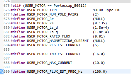
Here are my motor parameters

#define USER_MOTOR_TYPE MOTOR_Type_Pm // Motor_Type_Pm (All Synchronous: BLDC, PMSM, SMPM, IPM) or Motor_Type_Induction (Asynchronous ACI)

#define USER_MOTOR_NUM_POLE_PAIRS (2) // PAIRS, not total poles. Used to calculate user RPM from rotor Hz only

#define USER_MOTOR_Rr (NULL) // Induction motors only, else NULL

#define USER_MOTOR_Rs (0.0473498) // Identified phase to neutral in a Y equivalent circuit (Ohms, float)

#define USER_MOTOR_Ls_d (32.0e-6) // For Induction, Identified average stator inductance (Henry, float)

#define USER_MOTOR_Ls_q (32.0e-6) // For Induction, Identified average stator inductance (Henry, float)

#define USER_MOTOR_RATED_FLUX (0.008) // 0.0045 Estimated from back-EMF

#define USER_MOTOR_MAGNETIZING_CURRENT (NULL) // Identified magnetizing current for induction motors, else NULL

#define USER_MOTOR_RES_EST_CURRENT (1.5) // During Motor ID, maximum current (Amperes, float) used for Rs estimation, 10-20% rated current

#define USER_MOTOR_IND_EST_CURRENT (-1.5) // During Motor ID, maximum current (negative Amperes, float)

#define USER_MOTOR_MAX_CURRENT (3.0) // CRITICAL: Used during ID and run-time, sets a limit on the maximum current command output of the controller

#define USER_MOTOR_FLUX_EST_FREQ_Hz (200.0) // During Motor ID, maximum commanded speed (Hz, float). Should always use 5 Hz for Induction.

#define USER_MOTOR_FREQ_LOW (166) // Hz - suggested to set to 10% of rated motor frequency

#define USER_MOTOR_FREQ_HIGH (1667) // Hz - suggested to set to 100% of rated motor frequency

#define USER_MOTOR_FREQ_MAX (2000) // Hz - suggested to set to 120% of rated motor frequency

#define USER_MOTOR_VOLT_MIN (1.80) // Volt - suggested to set to 15% of rated motor voltage

#define USER_MOTOR_VOLT_MAX (12.0) // Volt - suggested to set to 100% of rated motor voltage

Please let me know if you have any suggestions for troubleshooting these errors. I've been trying many different combinations for the past week but have not yet found any success.

Best regards,

Chris

  • 1. The USER_SYSTEM_FREQ_MHz is not right with 90MHz for F28027F, it's 60MHz.
    2. Don't need set USER_MOTOR_FLUX_EST_FREQ_Hz to so high frequency, 40Hz~100Hz is ok for most motor, includes low inductance motor.
  • Good afternoon Yanming,

    Thank you for the quick reply. We've updated the settings to 60MHz and 100Hz, but are still having trouble identifying the inductance. What do you recommend for PWM frequency and tick per ISR?

    #define USER_SYSTEM_FREQ_MHz (60.0)

    #define USER_PWM_FREQ_kHz (60.0) //30.0 Example, 8.0 - 30.0 KHz typical; 45-80 KHz may be required for very low inductance, high speed motors

    #define USER_NUM_PWM_TICKS_PER_ISR_TICK (3)

    #define USER_NUM_ISR_TICKS_PER_CTRL_TICK (1) // 2 Example, controller clock rate (CTRL) runs at PWM / 2; ex 30 KHz PWM, 15 KHz control

    #define USER_NUM_CTRL_TICKS_PER_CURRENT_TICK (1) // 1 Typical, Forward FOC current controller (Iq/Id/IPARK/SVPWM) runs at same rate as CTRL.

    #define USER_NUM_CTRL_TICKS_PER_EST_TICK (1) // 1 Typical, FAST estimator runs at same rate as CTRL;

    #define USER_NUM_CTRL_TICKS_PER_SPEED_TICK (5) // 15 Typical to match PWM, ex: 15KHz PWM, controller, and current loop, 1KHz speed loop

    #define USER_NUM_CTRL_TICKS_PER_TRAJ_TICK (5) // 15 Typical to match PWM, ex: 10KHz controller & current loop, 1KHz speed loop, 1 KHz Trajectory

    #define USER_R_OVER_L_EST_FREQ_Hz (300)
  • Note that the table of identified parameters posted by James M. is for the same project and board we're testing. The inductances are consistency ~1e-13 using lab2c. The motor appears to be spinning well with a reasonable current draw, and the identified flux and resistances appear to be correct.

  • Right. Lab02c can work well on such motor. You can use 45kHz with 3 isr/control ticks, and you need to set right USER_MOTOR_RES_EST_CURRENT, USER_MOTOR_IND_EST_CURRENT and USER_MOTOR_MAX_CURRENT. It seems these three value is too small to run motor smoothly during identification process. You need to increase these values, and set USER_MOTOR_FLUX_EST_FREQ_Hz to 60Hz to enable motor run smoothly.
  • We updated our values as suggested and ran lab2c 3 times with the following results:

    The Lsd and Lsq seem very low. I would suspect we would get an error if we tried to use those values. What is involved in measuring those more accurately? 

  • The current is not enough yet to run motor smoothly, you should increase continuously to run motor again.

  • Good morning Yanming,

    Thanks again for your quick reply on this matter. We've increased the current to 2.0 amps in the last test, and the motor is spinning with this setting. How high do you recommend increasing the current in this case? Are there any other factors that may be causing this issue?
  • Used the following motor params:

    Got the following results from Lab2c:

    Lsd and Lsq seem way too low. How do we increase the test current to get better results? Thanks for your help.

  • Plot Settings

    I have attached some pictures of the phase A current from the data logger while running Lab2c. The current seems choppier than I would expect. Does this look correct?

  • Good afternoon Yanming,

    Jim has attached three graphs showing the measured IA current, which has been recorded by the 28027F processor, for the ramp up and flux estimation states. I see there are some cases where the current jumps. Can you verify this is the expected behavior for these two states?

    Best regards,

    Chris

  • Check out the inductance measurement channel A current waveform.

    Also check out the waveform during the Rampup phase

    Do these look right?

  • Any suggestions from the TI community? Yanming? We've tried increasing the Ls estimation current but have not had any success. What are you recommended next steps for troubleshooting? Do the graphs of Ia look correct for the different estimation states?

    Thanks,

    Chris

  • can you drag/drop your latest user.h into your reply and I will take a look
  • Good evening Chris,

    Good to hear from you again. You've been a huge help for us in the past with our previous motor controller project. Here's a copy of the user.h file. We've tried experimenting with several different USER_MOTOR_IND_EST_CURRENT and USER_MOTOR_FLUX_EST_FREQ_Hz settings, but have not been able to achieve a successful inductance estimate. Do the Ia graphs in the previous posts look correct to you? What do you recommend for the next debugging steps?

    Best regards,

    Chris

    75774.user.h

  • 6327.user.hI assume this is a completely custom board.

    Have you checked it out to insure proper pin mapping, current polarity, etc?

    Have you ID'd and run any other "standard motors"

    MotorWare v18 has proj_lab01 to help with hardware verification.

    Assuming all HW/SW settings are good...

    I don't see a bunch of changes that need to be made, but you can use this user.h

    Try motor ID again using proj_lab02c

    report the Rhf, Lhf, and Rs

    does the motor start spinning and ramp to 80 Hz = 2400 RPM?

    if it doesn't start up increase

    USER_MOTOR_RES_EST_CURRENT      (5.0)

    report the flux value

    does the motor keep spinning at 2400 RPM for the duration of the ID process?

    if it doesn't, increase

    USER_MOTOR_RES_EST_CURRENT      (5.0)

  • You seem to be be graphing 50 samples wide blocks at 1 Hz into a 400 sample graph. This will give you roughly 8 segments of unrelated data in your graph, I'm betting this is not what you intended. Check the configuration.

    Also a flux of 0.003 VpHz x 100 Hz gives ~ 0.3V. On an ADC_FULL_SCALE_VOLTAGE of 22.53V, that is just 1.3% of your ADC scale, 54 counts in 4095. That is not impossible to measure, but it is quite low and I would not expect a noisy board to be able to measure this.

    At the full 14 volts, this motor would run up to (roughly) 140.000 RPM (14 / 0.003 / 2 * 60) which seems rather high. It seems to me this motor and this board are not a very good fit.

  • Good afternoon Chris,

    Thank you for the suggestions. I took a step back and connected a more standard inductance motor, an Anaheim Automation BLY17 Series motor, but am still not achieving consistent identification. It seems to work perhaps 50% of the time. This motor is an 8-pole,  1.5Ohm, 2.1mH, and 2.7V/kRPM motor. The values I'm finding after a successful identification are 1.3 Ohms, 1.3mH, and 0.025V/Hz, which seem reasonable. But there seem to be two problems

    1) After solving for these parameters and re-setting Flag_RunIdentify = 1, the motor is not controlled well. There is lots of vibration and it becomes unstable at roughly 200RPM.

    2) It only solves for these parameters roughly 50% of the time. In other cases, the identified Ls is 1e-9H.

    I've modified the datalog to store 150 values x 3 phases (this seemed to be the limit for the 28027F chipset), and recorded a few sample images of the current during the Rs, Flux, and Ls identification stages. It doesn't appear to match the sine wave shown in the lab documentation, but perhaps I'm not recording enough samples. Any suggestions for adjusting the graph settings to help troubleshoot?

    Any additional thoughts on why it may be failing for this new motor? I did go back and run labs 1b and 1c and I can spin the motor in both cases. I've attached my latest user.h for review.

    Rs identification

    Flux identification

    Ls identification

    7360.user.h

    Thanks again for your support!

    Chris

  • I would say your hardware has some serious issues. You need to look closely at your voltage and current sense circuits. Insure kelvin ground connections. Make sure you aren't getting noise. When you do the offset calibration all three channels should be close to the same value. In your user.h your current offsets are a clear sign of hardware issues.
  • Good evening Chris,

    Thanks for the quick reply. We'll look more closely at the voltage and current sense circuits. How is the offset calibration performed? Is it simply taking one reading (or group of readings) with no current in the circuit in order to measure the bias? Would I see the same bias on a scope if I measured the ADC input on each of the current/voltage inputs directly (when not running)? If that's the case, it will be easy to confirm if the current/voltage biases are correct.

    Also note that we're using the latest DRV8323 chip, which has three current amplifiers. We had to create a custom drv8323.c based on drv8305.c, which included updating the register mapping. Are there specific commands or conditions that are sent to the DRV8301 or DRV8305 chips during the identification phases? Does the DRV chip have to be in a special state during identification phase?

    Thanks again for your support!

    Best regards,
    Chris
  • Chris,
    Please review SPRUHJ1 chapter 6.5.2

    no, there is not a special state for the DRV chip. Please note we did add support for DRV8323 through a SW download here:
    e2e.ti.com/.../635499
  • Good afternoon Chris,

    Thanks again for reviewing our case. After a thorough hardware review, we found that we were using a 2.048 Vref signal, but the DRV8323 requires Vref > 3 volts. Once we made this change, we're obtaining much more consistent current and voltage offsets. Despite this improvement in the offset biases, I'm still seeing the same issue with inductances being measured as 1e-9H perhaps 50% of the time. Note we are using Kelvin ground connections. What are you next suggested steps for troubleshooting? I've attached my most recent user.h for the Anaheim motor.5270.user.h

    //! \brief ADC current offsets for A, B, and C phases

    //! \brief One-time hardware dependent, though the calibration can be done at run-time as well
    //! \brief After initial board calibration these values should be updated for your specific hardware so they are available after compile in the binary to be loaded to the controller
    #define I_A_offset (0.973623335)
    #define I_B_offset (0.975451648)
    #define I_C_offset (0.989299715)

    //! \brief ADC voltage offsets for A, B, and C phases
    //! \brief One-time hardware dependent, though the calibration can be done at run-time as well
    //! \brief After initial board calibration these values should be updated for your specific hardware so they are available after compile in the binary to be loaded to the controller
    #define V_A_offset (0.318499684)
    #define V_B_offset (0.318760693)
    #define V_C_offset (0.316394270)

    All the best,

    Chris

  • I don't think this is your issue, but you can set both of these to (1)
    #define USER_NUM_CTRL_TICKS_PER_SPEED_TICK (5)
    #define USER_NUM_CTRL_TICKS_PER_TRAJ_TICK (5)

    are you still doing the ID on a low flux, low inductance motor like your first post? or are you actually using Anaheim_BLY171D?

    If you are using Anaheim_BLY171D and getting 1e-9 measurements there still must be something wrong with your HW.

    If you are using a low flux, low inductance motor, you need to make sure you update the USER_MOTOR values for that motor:
    #elif (USER_MOTOR == Anaheim_BLY171D)
    #define USER_MOTOR_TYPE MOTOR_Type_Pm
    #define USER_MOTOR_NUM_POLE_PAIRS (4)
    #define USER_MOTOR_Rr (NULL)
    #define USER_MOTOR_Rs (1.3000000000)
    #define USER_MOTOR_Ls_d (0.0013000000)
    #define USER_MOTOR_Ls_q (0.0013000000)
    #define USER_MOTOR_RATED_FLUX (0.0250000000)
    #define USER_MOTOR_MAGNETIZING_CURRENT (NULL)
    #define USER_MOTOR_RES_EST_CURRENT (0.5)
    #define USER_MOTOR_IND_EST_CURRENT (-0.5)
    #define USER_MOTOR_MAX_CURRENT (1.8)
    #define USER_MOTOR_FLUX_EST_FREQ_Hz (26.7)

    USER_MOTOR_FLUX_EST_FREQ_Hz (60.0) to (80.0) for high speed motors
    USER_MOTOR_MAX_CURRENT (1.8) // this will need to be much higher, just set it to (20.0) and you don't have to worry

    USER_MOTOR_RES_EST_CURRENT (0.5) // start with 10% of rated current and keep increasing until the motor is able to start spinning, reach EST_FREQ_HZ, and keep spinning for duration.

    use proj_lab02c
  • Hi Chris,

    Thanks again for your help on this project. I am using the Anaheim_BLY171D at this stage for troubleshooting, since this is a more common motor configuration. I'm still not able to successfully (repeatably) identify the inductance. I tried the higher speed and traj frequencies but it returned CTRL_ERROR when I tried to run the motor identification.

    I'm finding that the motor is spinning freely and without too much vibration during the Flux identification at 400rpm (10% of rate speed, e.g. 26.7Hz as defined in user.h), however, the motor is not spinning at all or spinning very poorly during the Ls identification. Can you provide any insight as to why it would succeed and run well during Flux identification but fail during Ls identification. For example, does one of these estimates rely on phase currents whereas the other relies on voltage measurements?

    What do you recommend for troubleshooting the suspected hardware issues that we're seeing during Ls identification. Would it be helpful to see graphs of phase currents and voltages during different segments of the identification.

    Best regards,
    Chris
  • there should be absolutely no issues in ID'ing this motor.

    I would recheck your current sampling circuit. You have the polarity correct in your software?

    you can use proj_lab01 to do some open loop checks
  • The motor spins in lab1c but I'm not sure what to expect from Ia current measurements. I've set up my data logger using

    datalog.iptr[0] = &gAdcData.I.value[0];   // datalogBuff[0]

    datalog.iptr[1] = &gAdcData.I.value[1];   // datalogBuff[1]

    datalog.iptr[2] = &gAdcData.I.value[2];   // datalogBuff[2]

    and set

    gMotorVars.IqSet_A = _IQ(0.5*USER_MOTOR_MAX_CURRENT);

    but I'm only seeing the current in my three graphs reach perhaps 0.1 Amps (where it should be half of max current or 0.9 Amps). Also note that the current from my power supply is measuring 0.5 Amps, but this is not the individual phase current.

    Would you expect &gAdcData.I.value[0] to reach IqSet_A value of 0.9 Amps?

    Also I found in the DRV8323 datasheet that the Isense / SOx outputs appear to be inverted. Where can I configured my current sense in hal.c to be inverted?

  • Where can I configured my current sense in hal.c to be inverted?

    review SPRUHJ1
    5.2.2
  • Thanks for confirming. I am using negative feedback (non-inverting pin) which is the default configuration. From my understanding, there are no additional changes necessary.

    Just confirming, I should use VREF_DIV = 1 so that Vref for amplifier is Vref / 2, allowing bidirectional current sense?
  • "use VREF_DIV = 1 so that Vref for amplifier is Vref / 2, allowing bidirectional current sense?"

    I'm not familiar with the use of this DRV device.

    There certainly appears to be something very wrong with your current sense though.
  • The values of inductance indicated are nearly accurate from my experience. Try defining the motor parameters if have any doubts.

  • Did you have any current waveform on oscilloscope for identification to show the issue? It seems that the motor didn't run smoothly. What's the rated current of the motor? You can set the USER_MOTOR_RES_EST_CURRENT and USER_MOTOR_IND_EST_CURRENT to 20%~40% of rated current to ensure the motor run smoothly.

  • Hi Chris,

    Just wanted to check in and see if these is any update from your side, please let me know if any questions. If no, we will close this thread.