This thread has been locked.

If you have a related question, please click the "Ask a related question" button in the top right corner. The newly created question will be automatically linked to this question.

CCS/F28M35H52C: Concerto GNU compiler support for ARM cortex m3 core

Part Number: F28M35H52C
Other Parts Discussed in Thread: CONTROLSUITE

Tool/software: Code Composer Studio

Hello,

I am trying to compile a simple blinky application using GNU ARM linero compiler and run it on Concerto arm cortex m3 core. I use a F28M35H52C based Concerto evaluation board (Follow below link)

  http://www.ti.com/tool/tmdsdockh52c1

But on the CCS studio if i select GNU linero compiler to build my application it pops up a warning saying the CCS will not automatically create any linker script or startup code which basically are critical initialization files to even to get a simple blinky application running. 

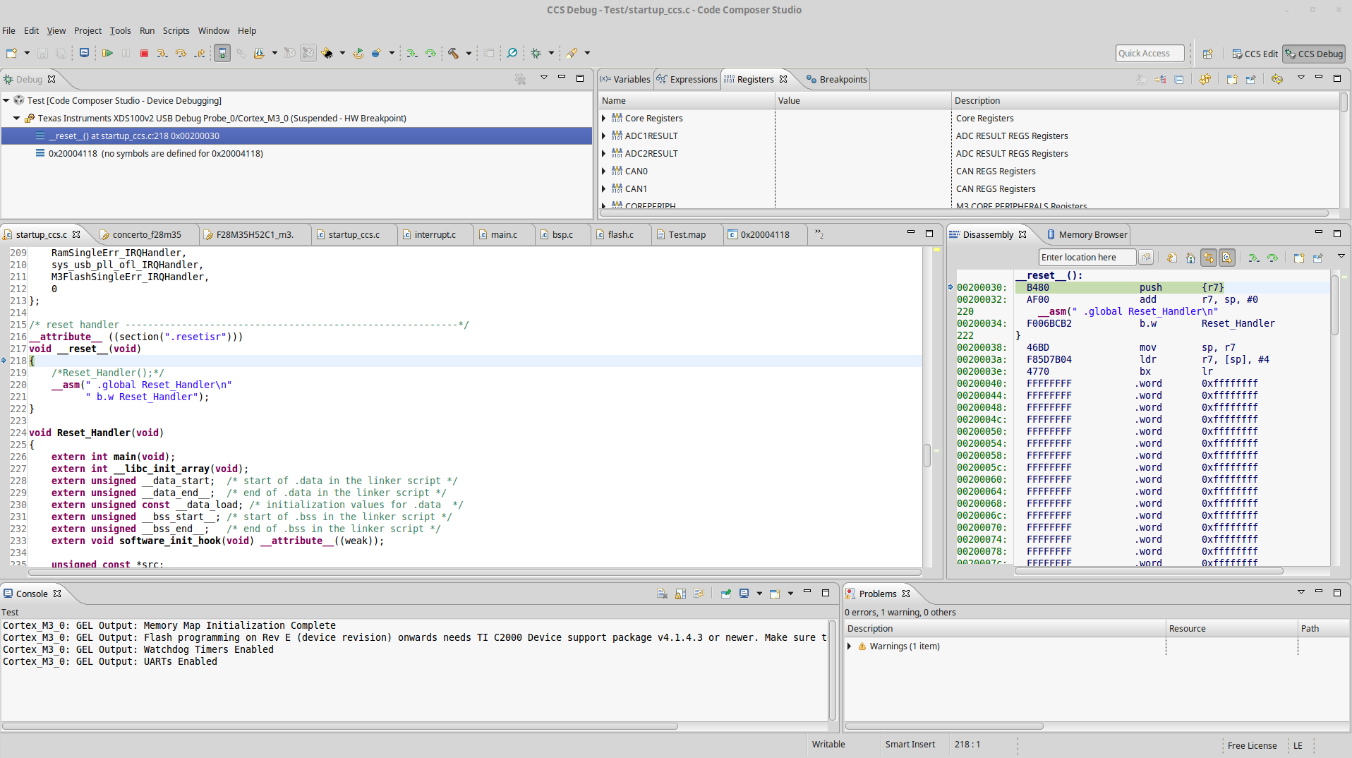
So i have now created my own linker script and a start up code for cortex m3 core similar to a article i read from a author on embedded.com website.

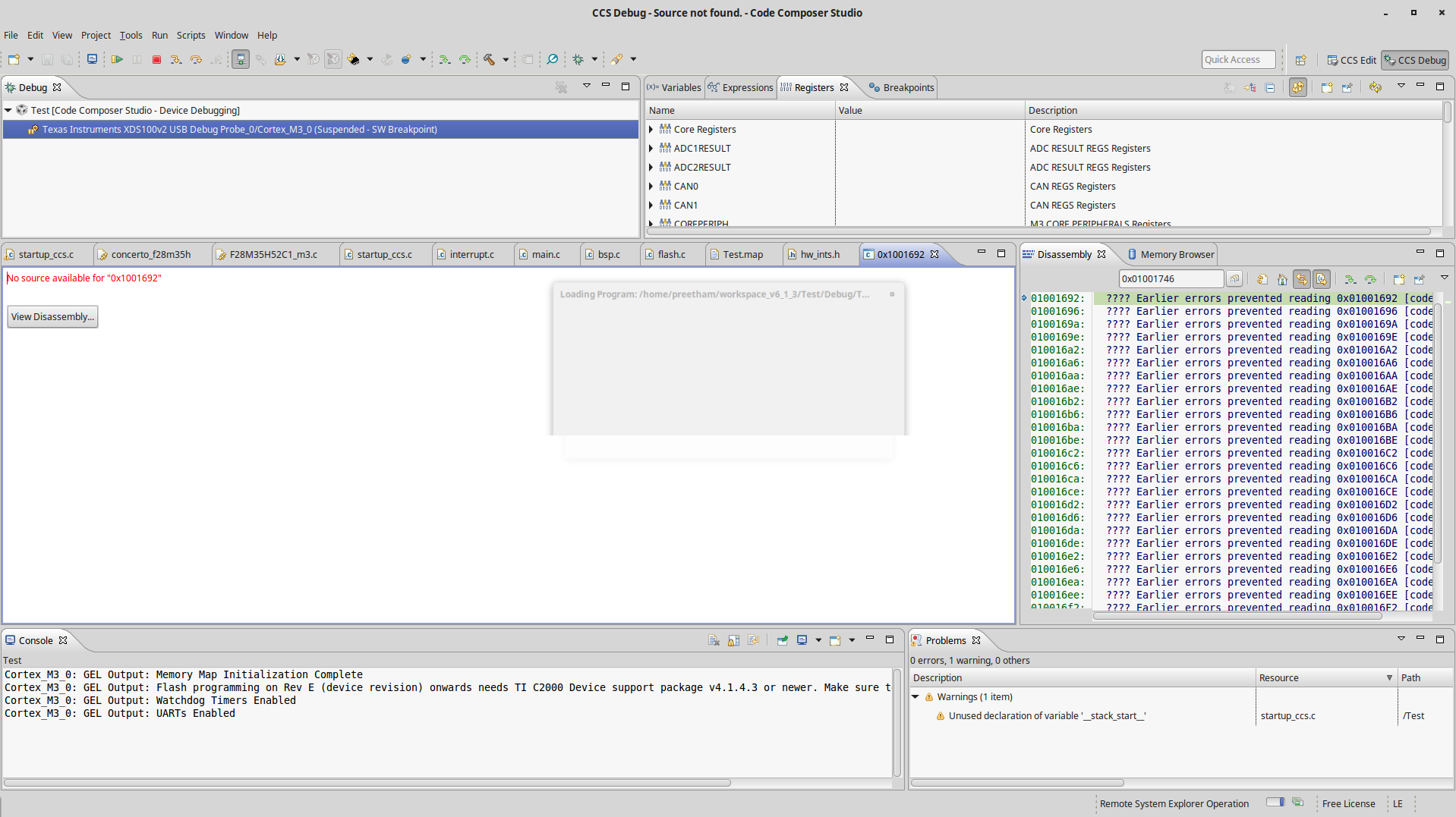
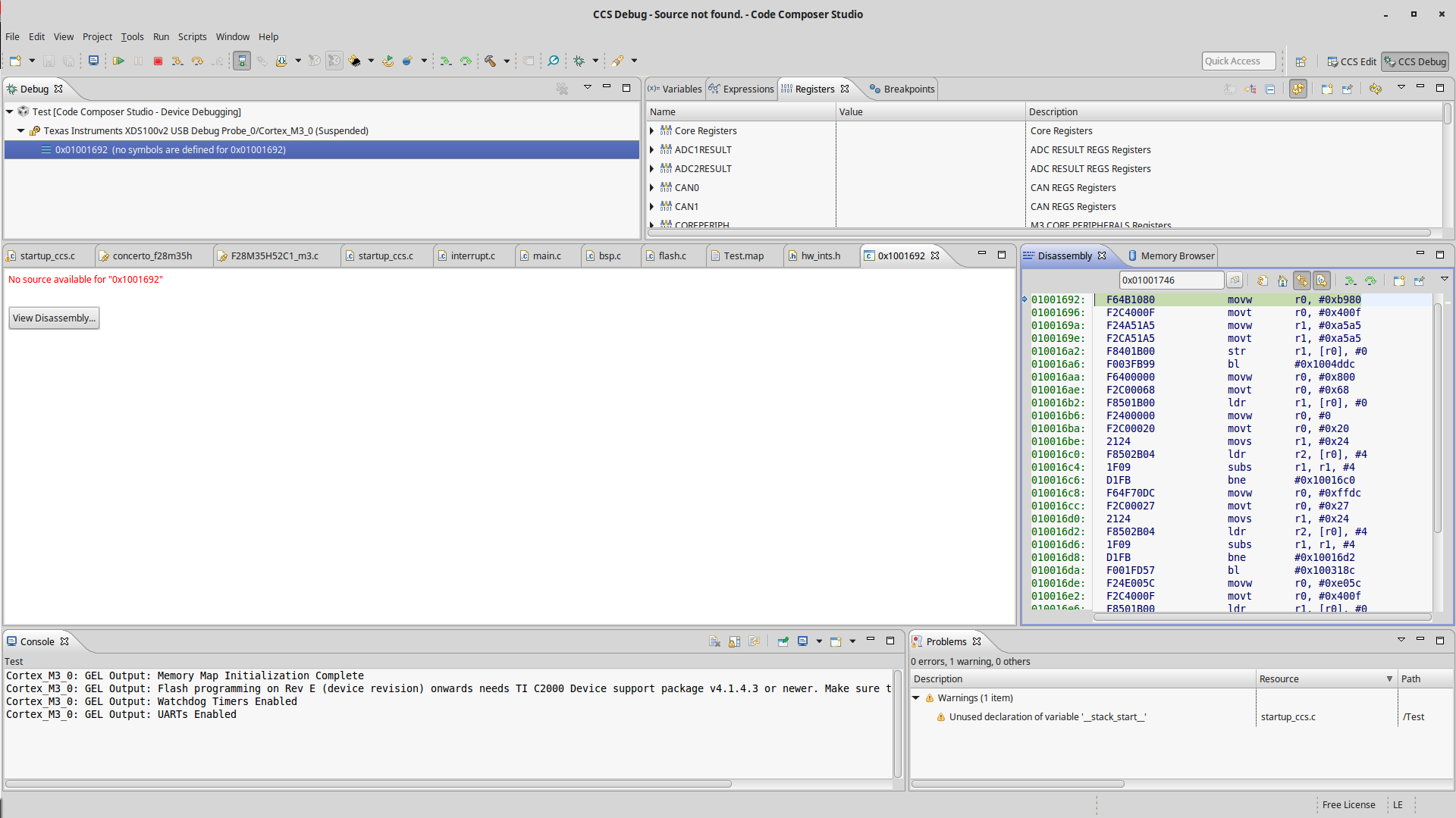
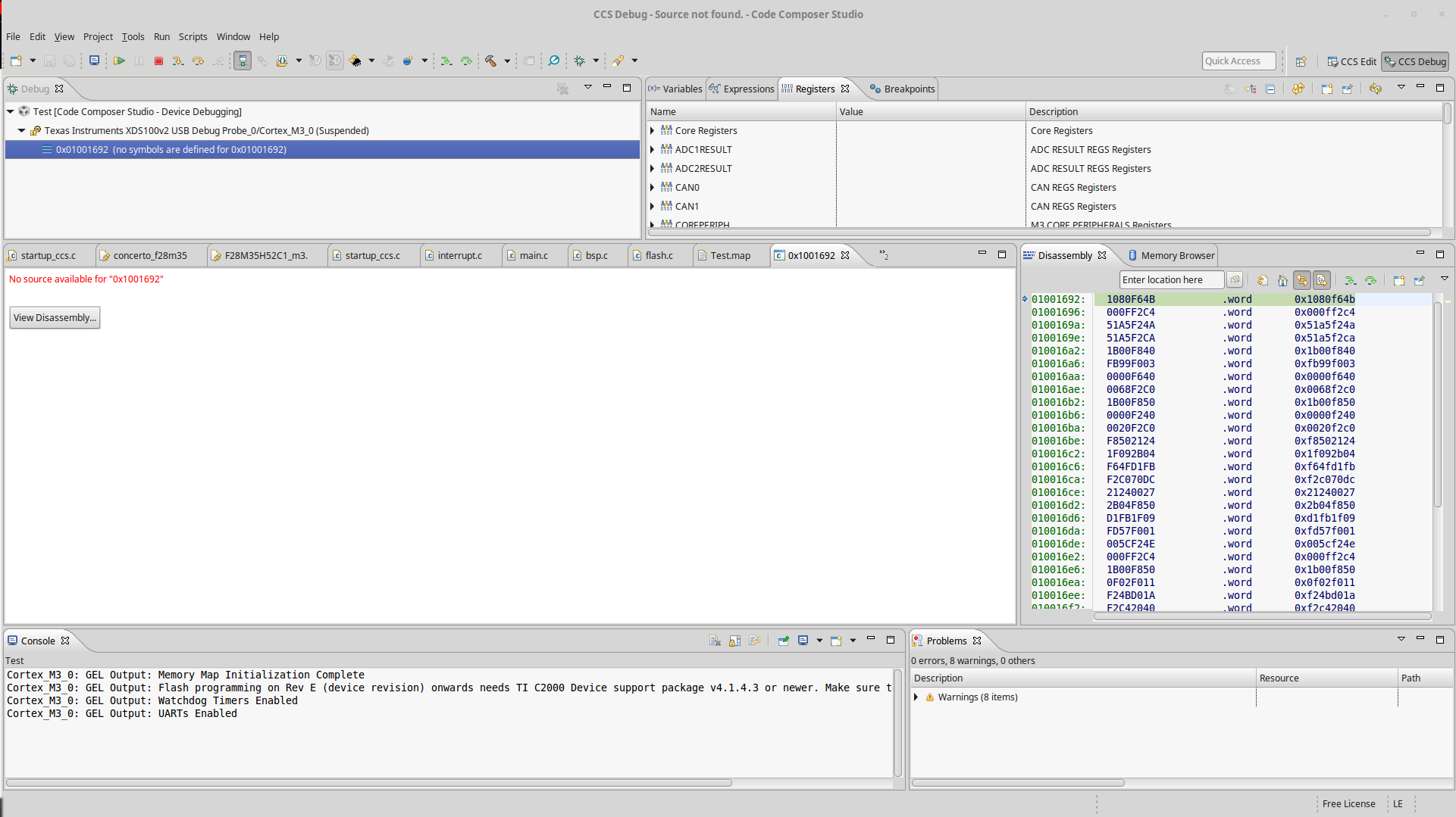
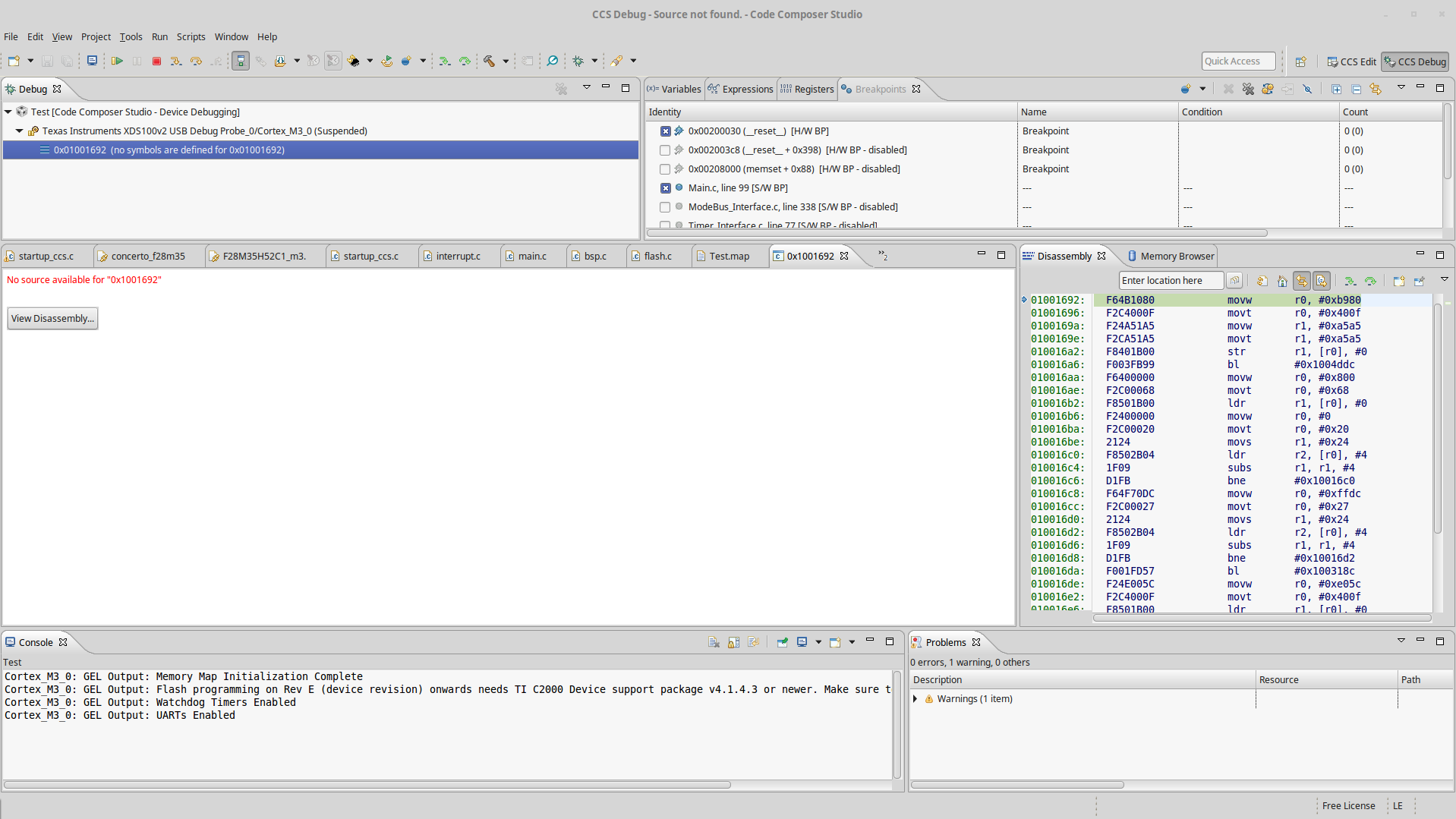
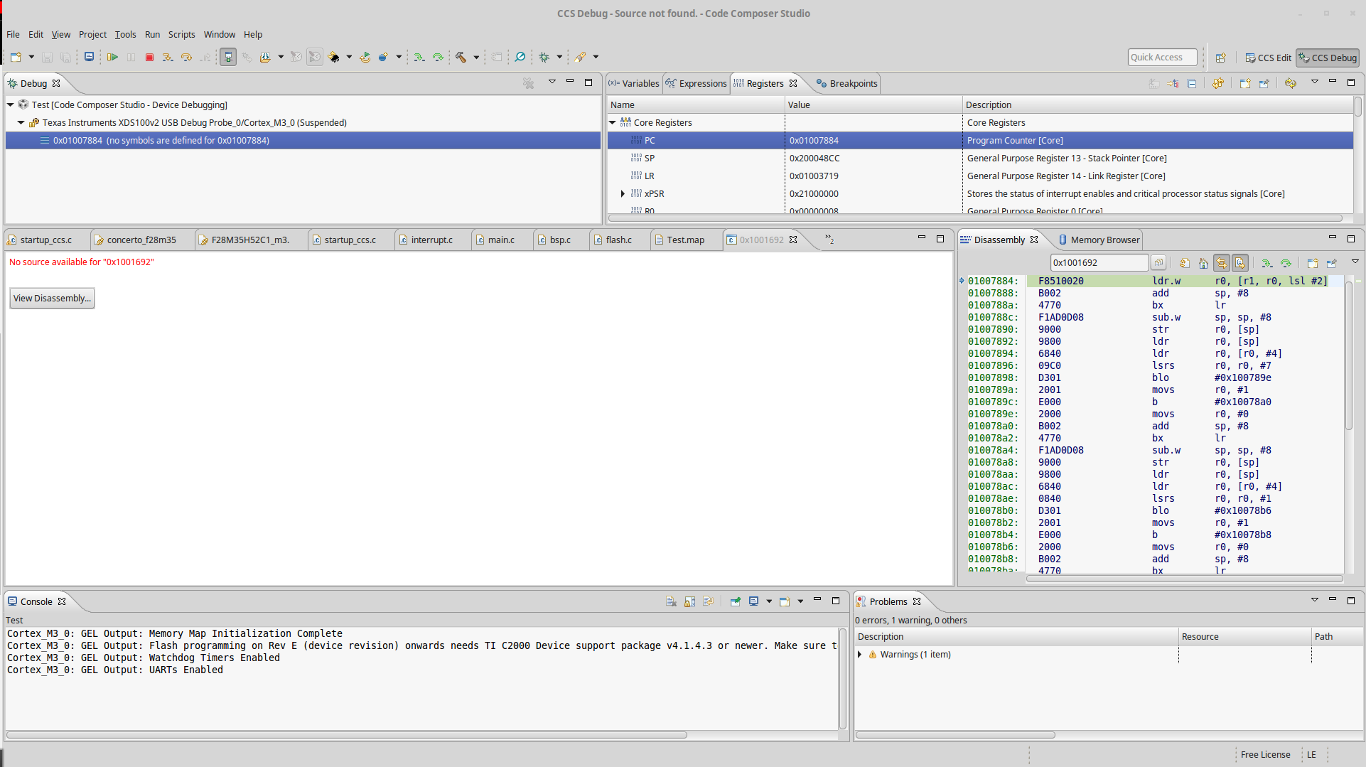
Now i am able to compile and link the project. But during debugging when i enter in to main and try to initialize the peripheral registers to trigger the on board LED, it could step over the RCGC2 register and when i try to step over the GPIODIR register the code breaks goes in to some undefined state (I think it resets). I think my linker script or startup function are correct. 

Really appreciate if someone could help me with this regards. I have attached my entire project which has the linker script and the startup code. 

The files are very generic and the linker script is named as "concerto_f28m35h2c.lds" and the startup file is named as "startup_ccs.c".

0410.Test.7z

  • Most Concerto customers build the ARM side code with the TI ARM compiler.  Have you considered that solution?

    Thanks and regards,

    -George

  • Hi George,

    Yes my first few projects with Concerto ARM core m3 development involved TI compilers.

    However now i am planning to port FreeRTOS on this core and FreeRTOS requires GNU compilers and hence i am desperately involved in getting a simple blinky program to work using GNU compilers.

    Thanks
  • Hi,

    I was taking a look at your code and, from a pure compiler and project standpoint, I don't see any problems with it.

    However, it seems you are not properly enabling the GPIO peripheral before trying to write data to it (the GPIODATA or GPIODEN), which causes an expected Hard Fault Exception.

    I found out this when, just before your call to GPIODATA, all GPIO Registers of all ports return the condition "Unable to Read"

    After stepping over the GPIODATA, the EXCEPTION bitfield of the xPSR register shows 0b000000011, which corresponds to the hard fault exception.

    Therefore, this quickly falls out of the Compiler or Tools expertise, given the device forum experts would know how to properly initialize the peripheral. 

    One tip perhaps is to try to adapt to GCC and rebuild the support library provided by TI and use the same APIs of the blinky example of controlSUITE.

    Library sources: C:\ti\controlSUITE\device_support\f28m35x\v210\F28M35x_common\source
    Blinky example: C:\ti\controlSUITE\device_support\f28m35x\v210\F28M35x_examples_Master\blinky\m3

    As George said, the use of GCC in this core is not officially supported by TI, therefore chances are your knowledge is ahead of us in the integration efforts, but hopefully the debug tips on this post may help you move forward. 

    Hope this helps,

    Rafael

  • Hi Rafael,

    Thanks for your detailed observation and reply. 

    Before i continue further, i made an other observation. Instead of initializing the LED from .c files if i copy the same piece of code in TI .gel file the LED lights up with no problem. I was totally perplexed at this point. But than i tried exactly what you have suggested and below are my results:  

    As you have suggested the use of TI supported library, I integrated TI peripheral library source code supported for concerto cortex m3 core and the result turned out to be successful and i am now able to light up the LED. I think it had to do something in initializing the entire system clock. 

    But there are two issues as of now:

    1. The LED works, however it looks like it executes only when i debug the code and if i power reset the board the application doesn't seem to run out of ROM.  

    2. As a next step i am now trying to initialize systick timer interrupt, where i am trying to toggle the on board LED's. To my surprise the interrupt never triggers. while trouble shooting i noticed that the systick count register is actually counting down but the interrupt is actually not firing. 

    Can you please help me in troubleshooting these two issue's ? Because if i can get a interrupt and application working off of ROM than i guess i would have a strong software base to smoothly continue my project further. Like you have stated in your reply, if i have to consult a different device expert support team can you please direct my query to the concerned team. I would really appreciate if i can get a device expert support in this regards as we are planning for a prototype product release very soon.  

    I have attached the revised project folder. 

    Thanks6232.Test.7z

  • Preetham,

    Preetham kashyap said:
    1. The LED works, however it looks like it executes only when i debug the code and if i power reset the board the application doesn't seem to run out of ROM. 

    To have the application start correctly on power up in stand-alone mode without debugger you will have to understand and make sure of below.

     >> the application has to be programmed into device flash memory

     >> The entry point of the application has to be programmed at the FLASH ENTRY POINT where the device boot ROM will branch to at the end of the boot.

    >>  The device boot mode pins should be set to boot to flash configuration. Device TRM boot ROM chapter has details on this, please refer to the TRM.

    The blinky sample example provided in TI ControlSuite supports all of the above for you to try. You can change the source code to use the GPIO that you want to toggle (connected to LED) and build the code.

    If you use Code Composer Studio, you can import the blinky example and build the FLASH configuration and check this out. Once you get this working with CCS, you can inspect the linker command files used and understand how the entry point sections are linked you can migrate to a different development environment. Using TI CCS, will cut down your development time and there is lot of support in forum for this as well.

    Preetham kashyap said:
    As a next step i am now trying to initialize systick timer interrupt, where i am trying to toggle the on board LED's. To my surprise the interrupt never triggers. while trouble shooting i noticed that the systick count register is actually counting down but the interrupt is actually not firing. 

    There is SYSTICK driverlib provided by TI in the controlSuite collateral  ( C:\ti\controlSUITE\device_support\f28m35x\v220\MWare\driverlib).

    There are other examples that initialize SYSTICK, you can refer to them to verify if you are doing the system set up correctly for SYSTICK.  For ex:  check this project. C:\ti\controlSUITE\device_support\f28m35x\v220\F28M35x_examples_Master\enet_lwip\m3

    You will have to register an interrupt handler and initialize NVIC BASE to user memory.  The timers example (C:\ti\controlSUITE\device_support\f28m35x\v220\F28M35x_examples_Master\timers\m3) shows how to enable and configure interrupts and you can do the same for systick using systick driver lib in your code.

    Having a TI CCS IDE environment simplifies checking all this out as well.

    Hope this helps.

    Best Regards

    Santosh Athuru

  • Hi Santosh,

    Thank you for the detailed reply. 

    I feel your answer was more inclined towards using TI control suite peripheral library and TI compiler solutions.

    However this is totally opposite to what i am trying to achieve. In my previous reply i have attached my project as a zip file, which i have compiled and linked using GNU compiler and all my questions are based upon using GNU compiler, which required me to write startup code and linker script for concerto cortex m3 core. 

    Here are my reply to your suggestions:

    1. The .lds linker file i have used in the project is very similar to the .cmd file used with TI linker tools. I also have verified that the FLASH ENTRY POINT should be at address 0x00203000 as per device TRM. But still i am not able to run this application as stand alone with out debugger. 

    May be you can run my attached project at your end and verify for yourself. 

    2. Regarding the Systick i see that the SYSTICK peripheral gets initialized perfectly, i can say this because i can verify while debugging that the SYSTICK COUNT register value actually decrements every clock cycle. But when the value reaches zero the Interrupt is never triggered. 

    I guess you can verify it yourself by using my project. 

    Now from my side i do not see anything wrong in terms of Startup code(Interrupt vector table) , linker script or initializing the system clock in main.c file.

    So this is where i need your device expert help in terms of what i could be missing in regards to my above two issues ?  

    Looking forward for your response. 

    Thanks

  • Preetham,

    Preetham kashyap said:
    However this is totally opposite to what i am trying to achieve. In my previous reply i have attached my project as a zip file, which i have compiled and linked using GNU compiler and all my questions are based upon using GNU compiler, which required me to write startup code and linker script for concerto cortex m3 core. 

    you need to look at the TI examples and understand what the start up code in examples is doing and how it is setting up the system. The device initialization should functionally remain same irrespective of the build tools used. Can you compare your device initialization flow with that from TI examples?

    You can compare the TI CCS build output files, for ex: the MAP file with the one you generate. If you use the same known working project (for ex: blinky) and build it with two different tool chains and compare the MAP files you should be able to see and make something out of similarities and differences.

    Preetham kashyap said:

    1. The .lds linker file i have used in the project is very similar to the .cmd file used with TI linker tools. I also have verified that the FLASH ENTRY POINT should be at address 0x00203000 as per device TRM. But still i am not able to run this application as stand alone with out debugger. 

    May be you can run my attached project at your end and verify for yourself. 

    as per device TRM section 6.5.7 the FLASH Entry Point is 0x200030. Please verify your linker. You need to also confirm if you have set the boot mode pins to boot to flash.

    Preetham kashyap said:

    Regarding the Systick i see that the SYSTICK peripheral gets initialized perfectly, i can say this because i can verify while debugging that the SYSTICK COUNT register value actually decrements every clock cycle. But when the value reaches zero the Interrupt is never triggered. 

    I guess you can verify it yourself by using my project. 

    Were you able to review the TI example code as I mentioned in my previous post? or do you have any other working example with interrupts?

    I suggest you look at the device TRM and example code and put a flow diagram on how the system needs to be initialized. Between TRM and examples we provide enough information for users to do this. Having this worked out is very important to continue with your project.

    Unfortunately we will not be able to run your project to verify this for you.  While we try to guide and help the users on the forums we also work on updating the collateral and releasing collateral for next generation MCUs. 

    Best regards
    Santosh Athuru

  • Santosh,

    I now have my interrupt working, however i still have not managed to get the application work in stand alone mode. 

    Meaning the application is not executed when i power cycle the board. 

    I have verified my FLASH Entry point is indeed at 0x00200030 and boot mode pins on the evaluation board is also set to M3 boot from flash mode. 

    Apart from this i have also modified my linker script such that ram start, ram size and ram run variables get values assigned accordingly.  Below is my linker code:

    /* memory map of F28M35H2C */

    OUTPUT_FORMAT("elf32-littlearm", "elf32-bigarm", "elf32-littlearm")
    OUTPUT_ARCH(arm)
    ENTRY(Reset_Handler) /* entry Point */


    MEMORY
    {

    /*ROM (rx) : ORIGIN = 0x00200000, LENGTH = 256k
    RAM (xrw) : ORIGIN = 0x20000000, LENGTH = 32K /*0x2000*/
    //RESETISR (rx) : ORIGIN = 0x00200030, LENGTH = 0x0008

    CSM_ECSL_Z1 : ORIGIN = 0x00200000, LENGTH = 0x0024
    CSM_RSVD_Z1 : ORIGIN = 0x00200024, LENGTH = 0x000C
    INTVECS (rx) : ORIGIN = 0x00200030, LENGTH = 0x01BC
    FLASHLOAD (rx) : ORIGIN = 0x00201200, LENGTH = 0x2E00
    FLASH (rx) : ORIGIN = 0x00204000, LENGTH = 0x7BF00
    CSM_RSVD_Z2 : ORIGIN = 0x0027FF00, LENGTH = 0x00DC
    CSM_ECSL_Z2 : ORIGIN = 0x0027FFDC, LENGTH = 0x0024
    C0 (rwx) : ORIGIN = 0x20000000, LENGTH = 0x4000
    C1 (rwx) : ORIGIN = 0x20002000, LENGTH = 0x2000
    BOOT_RSVD (rx) : ORIGIN = 0x20004000, LENGTH = 0x0900
    C2 (rwx) : ORIGIN = 0x20004900, LENGTH = 0x1700
    C3 (rwx) : ORIGIN = 0x20006000, LENGTH = 0x2000
    S0 (rwx) : ORIGIN = 0x20008000, LENGTH = 0x2000
    S1 (rwx) : ORIGIN = 0x2000A000, LENGTH = 0x2000
    S2 (rwx) : ORIGIN = 0x2000C000, LENGTH = 0x2000
    S3 (rwx) : ORIGIN = 0x2000E000, LENGTH = 0x2000
    S4 (rwx) : ORIGIN = 0x20010000, LENGTH = 0x2000
    S5 (rwx) : ORIGIN = 0x20012000, LENGTH = 0x2000
    S6 (rwx) : ORIGIN = 0x20014000, LENGTH = 0x2000
    S7 (rwx) : ORIGIN = 0x20016000, LENGTH = 0x2000
    CTOMRAM (rx) : ORIGIN = 0x2007F000, LENGTH = 0x0800
    MTOCRAM (rwx) : ORIGIN = 0x2007F800, LENGTH = 0x0800
    }

    /* The size of the stack used by the application. NOTE: you need to adjust */
    STACK_SIZE = 1024;

    /* The size of the heap used by the application. NOTE: you need to adjust */
    HEAP_SIZE = 256;

    SECTIONS {

    .isr_vector : { /* the vector table goes FIRST into ROM */
    KEEP(*(.isr_vector)) /* vector table */
    . = ALIGN(4);
    } >INTVECS

    .text : { /* code and constants */
    . = ALIGN(4);
    *(.text) /* .text sections (code) */
    *(.text*) /* .text* sections (code) */
    *(.rodata) /* .rodata sections (constants, strings, etc.) */
    *(.rodata*) /* .rodata* sections (constants, strings, etc.) */

    KEEP (*(.init))
    KEEP (*(.fini))

    . = ALIGN(4);
    } >FLASH

    .preinit_array : {
    PROVIDE_HIDDEN (__preinit_array_start = .);
    KEEP (*(.preinit_array*))
    PROVIDE_HIDDEN (__preinit_array_end = .);
    } >FLASH

    .init_array : {
    PROVIDE_HIDDEN (__init_array_start = .);
    KEEP (*(SORT(.init_array.*)))
    KEEP (*(.init_array*))
    PROVIDE_HIDDEN (__init_array_end = .);
    } >FLASH

    .fini_array : {
    PROVIDE_HIDDEN (__fini_array_start = .);
    KEEP (*(.fini_array*))
    KEEP (*(SORT(.fini_array.*)))
    PROVIDE_HIDDEN (__fini_array_end = .);
    } >FLASH

    .flashload : {
    . = ALIGN(4);
    }> FLASHLOAD

    RamfuncsLoadStart = LOADADDR(.flashload);
    RamfuncsLoadSize = SIZEOF(.flashload);

    _etext = .; /* global symbols at end of code */

    .vtable : {
    . = ALIGN(4);
    } >C1

    .stack : {
    __stack_start__ = .;
    . = . + STACK_SIZE;
    . = ALIGN(4);
    __stack_end__ = .;
    } >C1

    .data : AT (_etext) {
    __data_load = LOADADDR (.data);
    __data_start = .;
    *(.data) /* .data sections */
    *(.data*) /* .data* sections */
    . = ALIGN(4);
    __data_end__ = .;
    _edata = __data_end__;
    } >C1

    .bss : {
    __bss_start__ = .;
    *(.bss)
    *(.bss*)
    *(COMMON)
    . = ALIGN(4);
    _ebss = .; /* define a global symbol at bss end */
    __bss_end__ = .;
    } >C1

    PROVIDE ( end = _ebss );
    PROVIDE ( _end = _ebss );
    PROVIDE ( __end__ = _ebss );

    .heap : {
    __heap_start__ = .;
    . = . + HEAP_SIZE;
    . = ALIGN(4);
    __heap_end__ = .;
    } >C1

    /*ramfuncs : LOADADDR(FLASHLOAD),
    RUN = C0,
    LOAD_START( RamfuncsLoadStart ),
    LOAD_SIZE( RamfuncsLoadSize ),
    RUN_START( RamfuncsRunStart ),
    PAGE = 0*/

    .ramfuncs : {
    . = ALIGN(4);
    } > C0
    RamfuncsRunStart = LOADADDR(.ramfuncs);

    .flashinitram : {
    . = . + 1;
    . = ALIGN(4);
    } > C0

    PUTBUFFER : {

    }> MTOCRAM

    PUTWRITEIDX : {

    }> MTOCRAM

    GETREADIDX : {

    }> MTOCRAM

    GETBUFFER : {

    }> CTOMRAM

    GETWRITEIDX : {

    }> CTOMRAM

    PUTREADIDX : {

    }> CTOMRAM

    /* Remove information from the standard libraries */
    /DISCARD/ : {
    libc.a ( * )
    libm.a ( * )
    libgcc.a ( * )
    }
    }

    And inside my main file i also have :

    /* Copy time critical Flash setup code to RAM - InitFlash(). The
    * RamfuncsLoadStart, RamfuncsLoadSize and RamfuncsRunStart symbols are
    * created by the linker. */

    memcpy( &RamfuncsRunStart, &RamfuncsLoadStart, ( size_t )&RamfuncsLoadSize );

    Can you please provide me some hints on where else should i be looking at in order to resolve this issue.

    Looking forward for your response.

  • Preetham,

    The golden rule when booting stand-alone is to remember that the program has nothing loaded/initialized in RAM for it to function. Any initialized data in RAM has to be coming from flash and the runtime C libraries will take care of this before program reaches main(). Inspect your map file for all the sections that are being loaded into RAM and see if there are initialized locations for program to function, if yes, then they need to moved to flash into a .cinit section. Similar to the RAMFUNCS sections that the main code does a memcpy, which is for any functions that need to be run from RAM, there will be a copy for the initialized data as well.

    One thing to note here is, I mentioned .cinit section based on my experience with TI tools, but if you are using different tool chain and different C support libraries then the sections and the routines could be different.

    this one is easier to debug on Concerto, with CCS., below are the steps.

    1.> Load your application in flash, but don't run. The program control will stop at entry point or main().
    2.> Now open dis-assembly window to the flash entry point location and set a hard break point.
    3.> now do a debugger reset , this will reset the MCU and the program control will be at the reset entry point which is in ROM
    4.> now make sure the boot mode pins are set to boot-to-flash
    5>. RUN, this will run the ROM code which will decode the boot mode pins and boots to flash and the program control should hit the Entrypoint.
    6.> now if the program control hits the Flash entrypoint, but it doesn't reach main() then you have issues with CINIT sections, where not all constants are linked to flash.
    7.> If it reaches main then you can step through and debug where the problem is.
    8> but if at the end of step 5, if the program control doesn't reach the flash entry point then you need re-check the boot mode pins. There are very less chances that this is happening.

    Hope this helps.

    Best Regards
    Santosh Athuru
  • Also remember that applications [edit:should not use the RAM reserved for boot ROM execution, this is documented in the TRM and also shown in the TI linker command files that come with TI examples. If user chooses to re-purpose the boot ROM reserved RAM then it must be taken care that nothing in these locations has initialized data needed by the application to start.


    Best Regards
    Santosh Athuru

  • Hi Santosh,

    With almost a week of research i still could not figure out how i am missing to initialize the RAM section. My project has all that is necessary for FLASH to RAM copy of initialized section. 

    As a run time c library i am using libc.a. This should work rite ? 

    Also in my reset vector i copy all the flash data to RAM and zero fill my .bss section. Below is my reset vector code for your reference.

    void Reset_Handler(void)
    {
    extern int main(void);
    extern int __libc_init_array(void);
    extern unsigned __data_start; /* start of .data in the linker script */
    extern unsigned __data_end__; /* end of .data in the linker script */
    extern unsigned const __data_load; /* initialization values for .data */
    extern unsigned __bss_start__; /* start of .bss in the linker script */
    extern unsigned __bss_end__; /* end of .bss in the linker script */
    extern void software_init_hook(void) __attribute__((weak));

    unsigned const *src;
    unsigned *dst;

    //SystemInit(); /* CMSIS system initialization */

    /* copy the data segment initializers from flash to RAM... */
    src = &__data_load;
    for (dst = &__data_start; dst < &__data_end__; ++dst, ++src) {
    *dst = *src;
    }

    /* zero fill the .bss segment in RAM... */
    for (dst = &__bss_start__; dst < &__bss_end__; ++dst) {
    *dst = 0;
    }

    /* init hook provided? */
    if (&software_init_hook != (void (*)(void))(0)) {
    /* give control to the RTOS */
    software_init_hook(); /* this will also call __libc_init_array */
    }
    else {
    /* call all static constructors in C++ (harmless in C programs) */
    __libc_init_array();
    (void)main(); /* application's entry point; should never return! */
    }

    /* the previous code should not return, but assert just in case... */
    assert_failed("Reset_Handler", __LINE__);
    }

    I also checked my map file and all the necessary sections of RAM are initialized for program to function. 

    Now what i could not understand is .cint section and how i could do it on GNU linker script. Could you please elaborate more in this regards.  

  • Yes i know about this and i have taken care that RAM used for boot ROM is not used in my application.
  • Preetham,
    in your entry point code Reset_Handler(), at the end you directly call main() - can you refer to your tool chain documentation or other examples, if this has to be a _start or something like that, which in turn calls main()?

    for ex, the below page suggests to have it as _start?
    github.com/.../arm-none-eabi-gcc-4_6

    other way to find out, is to see what the tool chain takes as default entry point if you don't define the entry point as Reset_Handler? You should probably call that entrypoint in your Reset_Handler?

    if the linking is all verified, then it could be that you are not calling proper run time library init routine.

    can you also attach your map file, next time?


    Best regards
    Santosh Athuru
  • Hi Santosh,

    Firstly, I looked in to the __start() function and i am already performing all the basic functions inside my Reset_Handler() which are done inside __start().

    Only thing that i am not doing is call SystemInit() function. This will take care of controller specific initialization (like setting up clock source etc...)and in my case i am doing it in start of main just like its done in examples compiled using TI Tools.  

    Santosh Athuru said:
    other way to find out, is to see what the tool chain takes as default entry point if you don't define the entry point as Reset_Handler? You should probably call that entrypoint in your Reset_Handler?

    How can i try this ? 

    Santosh Athuru said:
    if the linking is all verified, then it could be that you are not calling proper run time library init routine.

    Like i mentioned above i saw inside __start() function from different project developed for STM32 controllers using GNU tools and i am just doing the same inside my Reset_Handler() function !! 

    Santosh Athuru said:
    can you also attach your map file, next time?

    Attached the map file.

    Test.map.7z

  • Preetham,

    Thanks for providing MAP file:

    I see that you are loading isr_vector section at 0x00200030 of length 0x1B0. This is not correct. At 0x00200030 location you need to have a small routine that branches to the application entry point. something like below. Boot ROM branches to 0x00200030 at the end of boot to below function which then calls into Reset_Handler. Assign isr_vector to some other flash location in your linker command file.

    void

    ResetISR(void)
    {
    // Jump to the CCS C Initialization Routine.
    __asm(" .global _Reset_Handler\n"
                                " b.w _Reset_Handler");
    }

    maybe fixing above fixes your problem. 

    Thanks for verifying the __Start and match it to your Reset Handler.  what about _mainCRTStartup function ? I see that this function is available in your tools (based on map file), I have read somewhere that this needs to be called as well? just check how this function is different from what you are doing in your entry point function (Reset Handler), does this function do anything different or anything extra before branching to main()

    Preetham kashyap said:

    Only thing that i am not doing is call SystemInit() function. This will take care of controller specific initialization (like setting up clock source etc...)and in my case i am doing it in start of main just like its done in examples compiled using TI Tools.  

    Santosh Athuru
    other way to find out, is to see what the tool chain takes as default entry point if you don't define the entry point as Reset_Handler? You should probably call that entrypoint in your Reset_Handler?
    Santosh Athuru
    if the linking is all verified, then it could be that you are not calling proper run time library init routine.
    Like i mentioned above i saw inside __start() function from different project developed for STM32 controllers using GNU tools and i am just doing the same inside my Reset_Handler() function !

    More notes below from your MAP file review:-

    Why is the ramfuncs below section of length 0x0? Do you not have any code that will be run from RAM? if I compile the blinky M3 example with in code composer studio, I get at least 0xbc length of RAM funcs. 

    .ramfuncs       0x20000000        0x0

    *(.ramfuncs)

                   0x20000000                . = ALIGN (0x4)

                   0x20000000                RamfuncsRunStart = LOADADDR (.ramfuncs)

    Also the .vtable is copied by TI run time library _cinit routine from flash to RAM. In your case bsed on your map file the vector table in flash is loaded in .isr_vector section, the data in this section needs to be moved to .table by start up code or you will have to initialize the vtable in RAM and assign the VTABLE OFFSET register accordingly.

    Also these sections, .preinit_array, .init_array seems to have some dependency with the start up code, check the _mainCRTStartup function.

    Best Regards

    Santosh Athuru

  • Hi Santosh,

    Santosh Athuru said:

    I see that you are loading isr_vector section at 0x00200030 of length 0x1B0. This is not correct. At 0x00200030 location you need to have a small routine that branches to the application entry point. something like below. Boot ROM branches to 0x00200030 at the end of boot to below function which then calls into Reset_Handler. Assign isr_vector to some other flash location in your linker command file.

    void

    ResetISR(void)
    {
    // Jump to the CCS C Initialization Routine.
    __asm(" .global _Reset_Handler\n"
                                " b.w _Reset_Handler");
    }

    maybe fixing above fixes your problem. 

    Firstly i do not understand why doing the way i currently do is wrong. Is it because the Reset_Handler is not sitting inside 0x0020030 ? 

    Secondly i tried the way you suggested above and the result did not improve the situation. Here is what i did:

    __attribute__ ((section(".resetisr")))    /* where this is sitting in 0x0020030*/
    void __reset__(void)
    {
    __asm(" .global Reset_Handler\n"
                " b.w Reset_Handler");
    }

    I can now verify while debugging that when i select to start my debugging secession at __reset__ it stops here and in the disassembly view i see that its at location 0x0020030. From here it branches off to Reset_Handler and then to main(). 

    However i still can not make it to run in stand alone mode. 

    Attached the revised map file for your references. 


    Santosh Athuru said:
    Thanks for verifying the __Start and match it to your Reset Handler.  what about _mainCRTStartup function ? I see that this function is available in your tools (based on map file), I have read somewhere that this needs to be called as well? just check how this function is different from what you are doing in your entry point function (Reset Handler), does this function do anything different or anything extra before branching to main()
    This particular function is from a pre-compiled GNU ARM toolchain library (crt0.o). Looks like the same file also has _start function as well also seen from map file. But i will try to investigate whats actually inside this function and if something important i will try to include it. 

    Santosh Athuru said:
    Yes, controller specific init you can take care in main(). Since you saw _start as the entry point for another project built with your tool chain, I strongly suspect that not having the entry point function at 0x00200030 like I mentioned above is the cause of the problem. But I still want to understand the _mainCRTStartup function usage.

    Again did not see any improvement as stated above and will try to figure out more about this _mainCRTStartup function. 

    Santosh Athuru said:

    Why is the ramfuncs below section of length 0x0? Do you not have any code that will be run from RAM? if I compile the blinky M3 example with in code composer studio, I get at least 0xbc length of RAM funcs. 

    .ramfuncs       0x20000000        0x0

    *(.ramfuncs)

                   0x20000000                . = ALIGN (0x4)

                   0x20000000                RamfuncsRunStart = LOADADDR (.ramfuncs)

    Here instead of .ramfuncs i am using .flashload section to store FlashInit and FlashSetup functions. As far as running code from RAM i am referencing to FlashInit function in my main.c file but please let me know if using FlashSetup function also has some benefit. 

    Santosh Athuru said:
    Also the .vtable is copied by TI run time library _cinit routine from flash to RAM. In your case bsed on your map file the vector table in flash is loaded in .isr_vector section, the data in this section needs to be moved to .table by start up code or you will have to initialize the vtable in RAM and assign the VTABLE OFFSET register accordingly.

    In this case as i am only trying to use SysTick ARM specific interrupt, i just register this particular interrupt routine like below

    IntRegister(FAULT_SYSTICK, SysTick_Handler);

    I see that inside IntRegister function the vector is copied from FLASH isr_table to RAM vector table and initialize the handler as needed. Please correct me if my understanding is wrong. 

    Could you also let me know what are the benefit of copying the entire vector table from FLASH to RAM. May be this is where i could be missing something !! 

    Santosh Athuru said:
    Also these sections, .preinit_array, .init_array seems to have some dependency with the start up code, check the _mainCRTStartup function.

    I completely ignored this as i did not have much need for it. Or do you feel its a critical missing part ? 

    1643.Test.map.7z

  • Preetham,

    what you mentioned about the isr_table being copied from flash to ram by int_register function is true. The function checks and copies and initializes the NVIC_TABLE offset correctly. Just inspect the 0x2000_2000 RAM location to see that vector table is correctly loaded after you call the int_register function.

    Please continue your investigation on _mainCRTStartup function and see if there is any code you need to handle to your Reset_handler or what happens if you branch to _Start or _mainCRTStartup from the new __reset__ function, instead of branching to Reset_Handler? does it get to main()?

    The way you were doing earlier is wrong because boot ROM at the end of booting when booting to flash, branches to 0x0020_0030 location and we expect a valid instruction here, like branch to reset_handler. If you are directly putting vector table here then they are not valid instructions but vectors so device will not start the application.

    Lets concentrate on below, 

    Preetham kashyap said:
    I can now verify while debugging that when i select to start my debugging secession at __reset__ it stops here and in the disassembly view i see that its at location 0x0020030. From here it branches off to Reset_Handler and then to main(). 

    Since you are now able to see a proper branch instruction at 0x0020_0030 location and with debugger connected you are able to reach to main(), I want you to do below. I'm listing out the steps assuming you are using CCS, but if you are using something else please map the steps to your IDE.

    A1.> put a break point at 0x0020_0030 location. You should be able to put the break point from dis-assembly window if you are using CCS.

    A2.> reset the CPU through debugger (not restart, but reset)- this should put the program control to device boot ROM reset handler. Don't worry about the sources not being available, you should see some instructions in dis-assembly window.

    A3.> The boot mode GPIO should be set to Boot -to-flash.

    A4.> hit run , this should run the code from the device boot ROM reset handler.

    A5.> now the break point at 0x0020_0030 should hit and CPU should halt. If it hits then you can be sure that program control is reaching the flash entry point even in stand alone.

    A6.> now put a break point at main()

    A7.> run again from [edit:]where it halted at step A5, do you reach main()

    A8.> if you reach main then continue debug and see where things are failing.

    if you don;t see any failure but device still doesn;t seem to run application in stand-alone, try below steps.

    S1.> program flash with your application.

    S2.> power off and power ON the board

    S3.> connect debugger

    S4.> load symbols for your application , don't load the full application again.

    S5.> continue from steps A1 to A8 from above and let me know what you see.

    Best Regards
    Santosh Athuru

  • Santosh Athuru said:
    what you mentioned about the isr_table being copied from flash to ram by int_register function is true. The function checks and copies and initializes the NVIC_TABLE offset correctly. Just inspect the 0x2000_2000 RAM location to see that vector table is correctly loaded after you call the int_register function.

    Yes i checked this in disassembly while running the application and the assembly instruction were same as what it was in ROM isr_vector section. Hence i believed the vector addresses would be re-mapped.

    After following your debugging instructions here are my observation and following screenshots of the observations. 

    Santosh Athuru said:
    A1.> put a break point at 0x0020_0030 location. You should be able to put the break point from dis-assembly window if you are using CCS.

    Here is what i see in disassembly window before flashing and during flashing process. Notice that there is no assembly instructions when i connect to the board. Does this mean i am not reading any BOOT ROM code ? 


    Now here is where i stop before running the application via debugger and i put a break point on 0x00200030 like you instructed. 

    Santosh Athuru said:
    A2.> reset the CPU through debugger (not restart, but reset)- this should put the program control to device boot ROM reset handler. Don't worry about the sources not being available, you should see some instructions in dis-assembly window.

    This is where it got interesting, now i started to see the assembly code at 0x1001692 address in the disassembly window !! 

    Santosh Athuru said:
    A3.> The boot mode GPIO should be set to Boot -to-flash.

    Always in Boot to flash option.

    Santosh Athuru said:

    A4.> hit run , this should run the code from the device boot ROM reset handler.

    A5.> now the break point at 0x0020_0030 should hit and CPU should halt. If it hits then you can be sure that program control is reaching the flash entry point even in stand alone.

    This never happens, meaning the execution does not halt or hit the breakpoint in 0x00200030 !!! It just keeps running in the unknown world of BOOT ROM i guess. 

    Santosh Athuru said:

    A6.> now put a break point at main()

    A7.> run again from [edit:]where it halted at step A5, do you reach main()

    A8.> if you reach main then continue debug and see where things are failing.

    Like i said above will never reach even the Boot to Flash code !!!

    Santosh Athuru said:

    if you don;t see any failure but device still doesn;t seem to run application in stand-alone, try below steps.

    S1.> program flash with your application.

    S2.> power off and power ON the board

    S3.> connect debugger

    S4.> load symbols for your application , don't load the full application again.

    S5.> continue from steps A1 to A8 from above and let me know what you see.

    Tried this as well and the result is same as above. Meaning when i try to load the symbols it now halts at 0x01001692 and says no symbols to load. But as seen before i start seeing some assembly code in the disassembly view and when i run it never runs application but just runs with in the BOOT ROM code. 

    Hope this will give you some clue on what might be going wrong on my end. Looking forward for your update. 

    Thanks

  • Preetham,

    Good, thanks for the snapshots they help. Lets concentrate on steps A1-A8. We need to get the CPU halting at flash entry point, 0x00200030.

    I don't see a valid break point at 0x0020_0030 location from your below snapshot. Try to right click at the location 0x0020_0030 and set HW breakpoint. You can view break points tab (next to the registers tab, above disassembly window and see if there is a valid break point).

    can you try again and follow the steps? whne you send the below snapshot next time, can you show the break points tab?

    Also try to scope the Boot mode select pins and make sure they are HIGH? let me know if they are high and you have the break point set correctly and after you do CPU reset (the chip button) and run (play button) you don't see CPU halted at break point at 0x0020_0030 location.

    Preetham kashyap said:

    Now here is where i stop before running the application via debugger and i put a break point on 0x00200030 like you instructed. 

    Preetham,

    [for reference below steps again] 

    A1.> put a break point at 0x0020_0030 location. You should be able to put the break point from dis-assembly window if you are using CCS.

    A2.> reset the CPU through debugger (not restart, but reset)- this should put the program control to device boot ROM reset handler. Don't worry about the sources not being available, you should see some instructions in dis-assembly window.

    A3.> The boot mode GPIO should be set to Boot -to-flash.

    A4.> hit run , this should run the code from the device boot ROM reset handler.

    A5.> now the break point at 0x0020_0030 should hit and CPU should halt. If it hits then you can be sure that program control is reaching the flash entry point even in stand alone.

    A6.> now put a break point at main()

    A7.> run again from [edit:]where it halted at step A5, do you reach main()

    A8.> if you reach main then continue debug and see where things are failing.

    Best Regards

    Santosh Athuru

  • Hi Santosh,

    Sorry for the delay, Below are the revised snapshots and corresponding steps that i perform:

    1. I connect to the target by clicking on Run -> Connect Target


    2. Now i load the .out file by clicking Run -> Load -> Load Program

    3. After the image is loaded i reach to __reset__ (if mentioned to sto at __reset__) i see something interesting in the function stack section.

        The jump to address 0x00200030 happens from address 0x20004118 where no symbols are defined ??


    4. Now before i click the Resume button, i placed a breakpoint on the address 0x00200030 in Disassembly window and clicked CPU reset button.

    5. Once i click the CPU reset button this is where i halt

    6. Now if i click on resume !!! Its never halted at 0x00200030 address ??

    Hope these snapshots are more clear than the previously shared ones. Please let me know your thoughts.

    Thanks 

  • Preetham,

    Preetham kashyap said:

    3. After the image is loaded i reach to __reset__ (if mentioned to sto at __reset__) i see something interesting in the function stack section.

        The jump to address 0x00200030 happens from address 0x20004118 where no symbols are defined ??

    yeah, I'm not yet sure why the call stack is showing 0x20004118 here. Lets ignore this for a bit until we get to the actual problem. we will get back to this once we figure out boot to flash entry point.

    step 5, looks ok to me.

    Preetham kashyap said:

    Now if i click on resume !!! Its never halted at 0x00200030 address ??

    can you clarify at step 6 you click the play button , the one left to the PAUSE button?

    at step 6, if you pause the MCU, where do you see the PC is at? do you monitor the XRSn pin on an Oscilloscope to see if it is toggling?

    At step 6, since it is not hitting the break point at flash entry point, can you pause the MCU and let me know the value you see at location 0x20004000? As per section 6.5.5.3 of TRM, there is a M-Boot ROM boot status that we can monitor to see what went in the boot ROM when you run the MCU after reset.

    Best Regards
    Santosh Athuru

  • Preetham,
    let me know if you have any updates, just following up.

    Best regards
    Santosh
  • Hi Santosh,

    Sorry for the delay, I am tied up with a different task this week.  I will definitely get back with a update On Monday.

    Thanks

  • Hi Santosh,

    Here are my observation in regards to BOOT ROM status value:

    Santosh Athuru said:
    can you clarify at step 6 you click the play button , the one left to the PAUSE button?

    The first image is running the application from the debugger and i do not see any value at location 0x20004000 ???

    This is a situation where i System Reset before running it from the debugger with a break point at 0x00200030. This is to answer your question weather or not i press the resume button .

    This is where it stopped when i pressed the pause button. 

    Santosh Athuru said:
    At step 6, since it is not hitting the break point at flash entry point, can you pause the MCU and let me know the value you see at location 0x20004000? As per section 6.5.5.3 of TRM, there is a M-Boot ROM boot status that we can monitor to see what went in the boot ROM when you run the MCU after reset.

    Santosh Athuru said:
    at step 6, if you pause the MCU, where do you see the PC is at? do you monitor the XRSn pin on an Oscilloscope to see if it is toggling?

    I have not checked the real signal value on XRSn pins !!! But the DIP switches on the evaluation board are all in up position and also i could run the TI control suite examples in stand alone mode. But i will try and give you some scope screen shots soon.   

    Hope these screenshots are helpful enough. 

  • Preetham,
    From your snapshots above, the boot status 0x0000107 indicates that the device has started Parallel boot and it happens when all the boot mode select pins are pulled LOW. Flip the boot mode select pins to HIGH and device should hit the break point at 0x0020_0030 (flash entry point).

    Best regards
    Santosh Athuru
  • Hi Santosh,

    OMG.....This was the problem all these days !!!

    Its working now.....Thank a lot for your help and patience. Really appreciate it.

    But i am curious now, how does the control suite applications compiled with TI compiler works in stand alone with BOOT pins pulled low ??

    Thanks
  • Preetham,
    thanks for the confirmation, I believe your debug went through very informative and useful stages and you didn't start with just this problem. So this is very good progress.

    The controlSuite examples or non-controlSuite examples they should behave same. Device will not boot to flash unless the boot mode select pins default to flash boot option. Check the board and monitor the boot mode pin select values on a scope and compare it against the device TRM boot mode table and you should see a reason if they are booting to flash.

    For now, let me know if we can close this post. I see that you have a new design question in another forum post and we can continue there. But if you still need to work through the boot and start up code, please feel free to continue.

    Best Regards
    Santosh Athuru
  • Hi Santosh,

    Santosh Athuru said:
    The controlSuite examples or non-controlSuite examples they should behave same. Device will not boot to flash unless the boot mode select pins default to flash boot option. Check the board and monitor the boot mode pin select values on a scope and compare it against the device TRM boot mode table and you should see a reason if they are booting to flash.

    I think i have to make myself clear about what i read about different bootpin options from the Concerto workshop documents. So i will do that and probably have a scope attached and get myself more familiar with this option. 

    Santosh Athuru said:
    For now, let me know if we can close this post. I see that you have a new design question in another forum post and we can continue there. But if you still need to work through the boot and start up code, please feel free to continue.

    I guess we can close this post and as i make some progress in this regard i will probably create a new thread if that's a good way to do it, if not we can have this post open. But i guess you can decide can take a decision. 

    Thanks

  • Preetham,
    Thanks. Lets close this post and please open another one if you need further help with development.

    Best regards
    Santosh Athuru