This thread has been locked.

If you have a related question, please click the "Ask a related question" button in the top right corner. The newly created question will be automatically linked to this question.

TMS320F28377D: TMS320F28377DZWT

Part Number: TMS320F28377D
Other Parts Discussed in Thread: SN74AHCT245, SN74HCT245

What is the output current of TMS320F28377DZWT as PWM output GPIO port (gpio145-gpio168)?What is the resistance between SN74AHCT245 and PWM back end?What is the resistance between the PWM back end and SN74HCT245?

  • The maximum output current for this device's GPIOs are 20mA. What do you mean by the resistance between "PWM back end and SN74HCT245"? The SN74HCT245 also has the following output current characteristics.

    http://www.ti.com/lit/ds/symlink/sn74ahct245.pdf

    Page 4.

    If you are directly connecting the PWM pin to SN74HCT245, the resistance between them is insignificant.

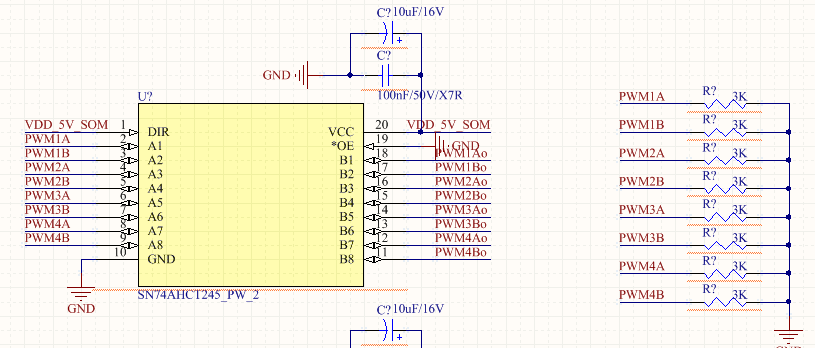
  • If the SN74AHCT245 transceiver is used to enhance the drive capacity of PWM and convert the TTL level (3V) of GPIO to CMOS level (5V), is a resistance required between the PWM output end of TMS320F28377DZWT and the SN74AHCT245 transceiver?If resistance is required, what is the magnitude of the resistance resistance?The specific circuit is shown in the figure

  • Here is my input:
    1. Those resistors are not series between PWM output and SN74AHCT245. Those are pull down resistors. Basically you can put them there for when the PWM signal is not present on the pin and the pin is floating so you're trying to force its state to be LOW. When you have configure the device to drive the PWM pin, their presence is not required. So this depends on whether your system requires the signals out of the pins to be LOW on power on.

    2. If these resistors are required (application specific), then a safe value is 10k, its high enough in resistance to not draw too much current and low enough to not create voltage dividers with the output and input pins.