Other Parts Discussed in Thread: C2000WARE, C2000WARE-DIGITALPOWER-SDK, POWERSUITE, SFRA
Hello everyone,
This thread follows my previous about tidm-1000 first launch. I have multiple questions :
1/ What is the link between the .c code and the "kit.xml" ? I have understood that the .cfg modify the .xml but I don't understand how the xml modify the code.
2/ In the .cfg sheet, we can choose between 4 builds. Does each build is independant or do we need to configure all of them for using build 4 ? I am asking this because I can't choose loop with the scrollbar menu :
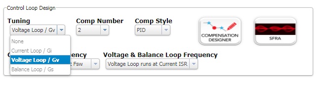
If I want to configure voltage loop I have to choose build 3, idem for Gi and Gs with builds 2 and 4.
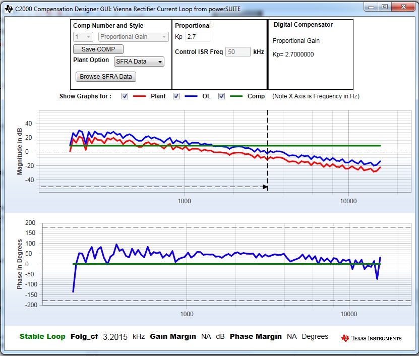
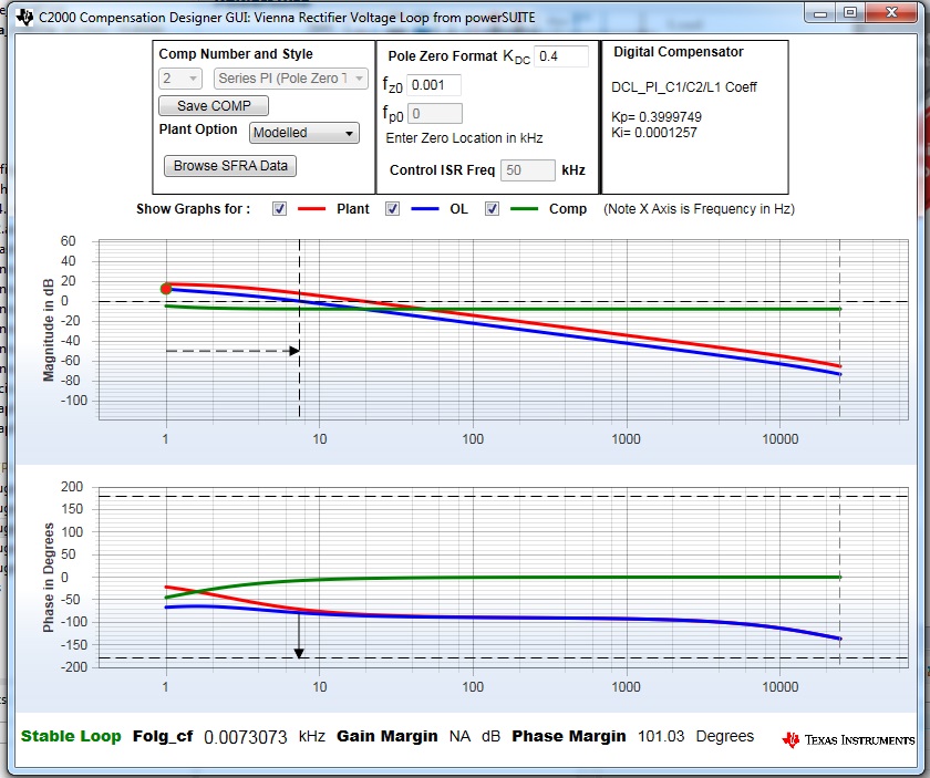
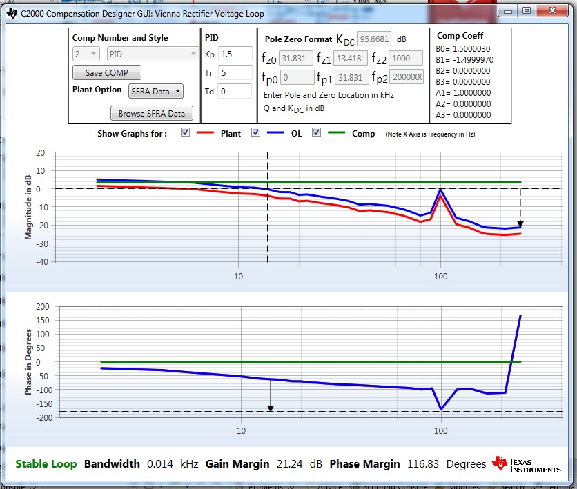
3/ Like the question 2, I can't change neither "Comp number" nor "Comp style", I don't know why. Moreover In build 2, with a P correcter I have also a Ti coeff in the compensator designer and in build 3 I have no choice to use PID (different from the documentation ...maybe it's another version) :
4/ In build 1 openloop, all phasis are bypassed (all dutycycles are the same) ... Is it not dangerous ?
5/ At page 41 of TIDUCJ0D, vBusRef is equal to 1.32 which is correspond to 600v/454v = VBUSREF_Voltage / VsenseMaxAC.
I think it's linked to PU values but why assume that VsenseMaxAC is equal to VbusSenseMax (454 and 717v in our case) ? I still can't understand why this isn't a problem to make that.
6/ It's not a question but maybe there is a small bug in the cfg page : the button "save" doesn't work.
I am asking all this because I have good results on AC current in build 3. I am using a 290ohm load instead of 500 ohm but before increase all gains I want to know what I am doing.
Thank you very much and have a nice day,
Best regards,
Jérémy