This thread has been locked.

If you have a related question, please click the "Ask a related question" button in the top right corner. The newly created question will be automatically linked to this question.

TMS320F28335: C2000™ microcontrollers forum

Part Number: TMS320F28335
Other Parts Discussed in Thread: OPA4170

Hi,

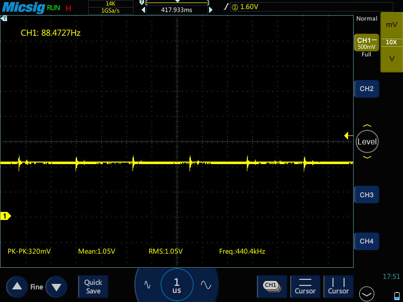
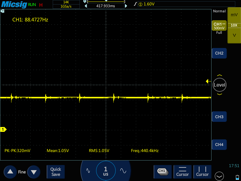
I have arranged parallel 100pF or 22pF capacitor on the input side of ADC. Which generate oscillate input for ADC.

I request you so kindly provide us your valuable suggestion to unwanted oscillated input for ADC. so we can move forward our design 

Below image for your reference

Regards,

Chirag Rana

  • Chirag,
    Wanted to clarify a few point with regard to the above to help me understand the issue better:

    Q1)Assume the scope plot is taken when the ADC is sampling, can you also show the plot with the ADC not sampling(C28x halted) so I can understand what the native voltage should be?

    Q2)Can you also share the ADC results that correspond to the scope plot you have shown in the original post?

    Best,
    Matthew
  • Hi Matthew,

    We have circuit Op-Amp OPA4170  output voltage measured in ADC,
    Condition 1:  I have arranged parallel 100pF or 22pF capacitor on the input side of ADC. Which generate oscillate input with different input range with measured ADC samples from the ADC as per below table. 

    OP-Amp Output Voltage Measured in ADC Sample
    0.50 540-820
    1.00 1160 - 1490
    1.50 1985-2288
    2.00 2512- 2820
    2.50 3312- 3680
    3.00 4000-4096

    This plot is 1.00 volt of measured in CRO. 

    Condition 2: If i have remove parallel capacitor then after measured ADC input is there almost stable ADC sample mention in below table.

    Input (Volt) ADC Sample
    0.5 680-699
    1 1440-1449
    1.5 2070-2078
    2 2765-2778
    2.5 3482-3496
    3 4065-4095

    This plot is 1.00 volt of measured in CRO. 


    Condition 3: No any input on ADC with parallel capacitor, But behavior same as condition 1 plot. 


    I request you so kindly provide us your valuable suggestion to unwanted oscillated input for ADC.


    Regards,

    Chirag Rana

  • Hi Matthew,

    Please ignore condition 1 plot  and consider plot 3 for condition 1 & 3 both are same behavior with parallel capacitor.

    I request you so kindly provide us your valuable suggestion to unwanted oscillated input for ADC.

    Regards,

    Chirag Rana

  • Chirag,

    There are a few things we can try, it might be best to see if we can simulate the circuit and reproduce the results you see in the real world.

    We have our own SPICE based tool that is free to use, and has most TI devices already populated http://www.ti.com/tool/TINA-TI   

    You can add the OPA directly, along with your caps, and then use the input model of the ADC found in the F28335 datasheet.  If we can get the same node as probed by the scope to exhibit the same behavior then we can optimize in the tool, vs iterating on the PCB.

    I looked at the OPA datasheet, and there is a recommendation to add a small series resistance(25 ohm) when driving larger capacitive loads.  I'm not certain this is needed here, but wanted to raise the point in general, as most amps struggle with cap loads.

    The fact that you are able to remove the 22pf cap and things get better/sine wave goes away, perhaps there is a mismatch in the cap type, NPO/COG/X7R/etc, and there is some effective resistance(ESR) that is causing the oscillation.

    I've not seen parallel caps used on the amp output, typically I see this on power supplies to give some filter protection on the input rail.

    Best,
    Matthew

  • Wanted to see if you had additional information based on my previous post? I'm going to mark as resolved, but feel free to reply and it will re-open the post.

    Best,
    Matthew