This thread has been locked.

If you have a related question, please click the "Ask a related question" button in the top right corner. The newly created question will be automatically linked to this question.

CCS/INSTASPIN-BLDC: The voltage sense circuit and the filter frequency setting

Part Number: INSTASPIN-BLDC
Other Parts Discussed in Thread: TIDA-00916, MOTORWARE

Tool/software: Code Composer Studio

Hi,

I am confused about the filter frequency setting in the voltage sense circuit.

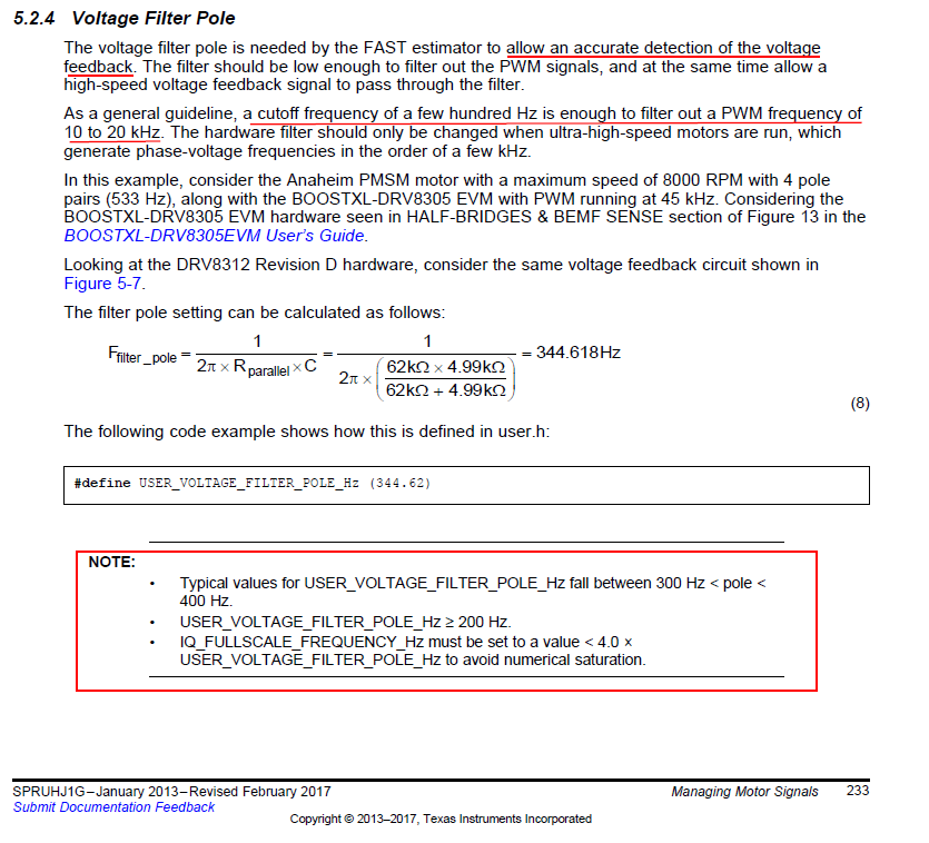
The InstaSpin-foc relates that the typical values for USER_VOLTAGE_FILTER_POLE_HZ fall between 300Hz < pole<400Hz and the maxim electrical frequency in this example is 533 Hz. You may refer to the figure below.

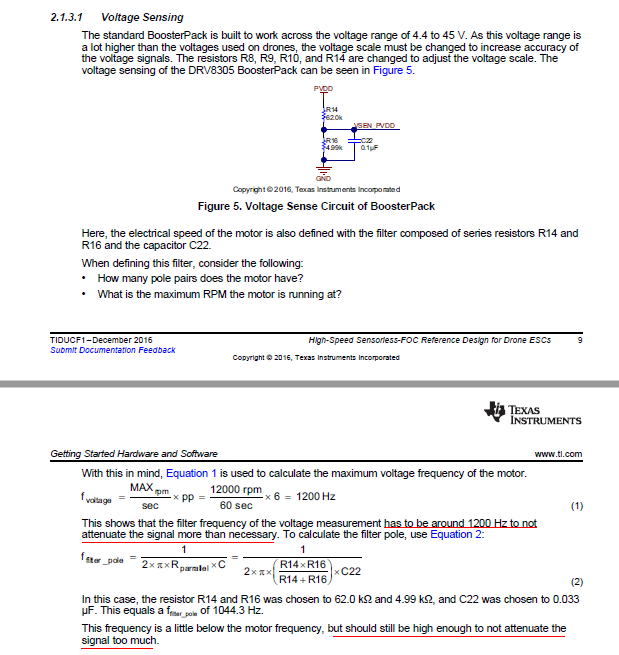
And in the datasheet of TIDA-00916,it relate that the frequency should be a little below the motor frequency but should still be high enough to not attenuate the signal too much(Page 10).

I am really confused by the two explains and  I think there are contradictory. And My view is that the second explain and its corresponding setting method may be more reasonable.So,if the maxim frequency of my system is 1500 Hz, the filter frequency should be set around 1500 Hz. And further more, I want to know how the filter frequency will influence my system if the frequency be set too low.

Thanks.

  • The phase output voltage is PWM waveform, The first thing you have to consider is how to get an clean analog output voltage signal from PWM waveform. Generally, the cut-off frequency should be less than 1/20 of PWM frequency to attenuate switching frequency. Surely, the phase is delayed and amplitude is decreased compare to original signal at that cut-off frequency.
    You don’t worry about that because InstaSPIN-FOC compensate the phase and the amplitude based on your input parameter(USER_VOLTAGE_FILTER_POLE_Hz).

    For example, in the following user case,
    - output frequency: 1500Hz
    - PWM frequency: 15KHz

    You can choice the filter pole as follower.
    F_filter_pole < (15KHz / 20)
    F_filter_pole > (1500Hz*1.1 / 4) //1.1 is comupation margin

    So, ideal pole design will be
    412.5Hz < F_filter_pole < 750Hz
  • Thanks.So the datasheet showed below may have some problem in the setting of the filter frequency of the voltage sensing. And further more,the USER_VOLTAGE_FILTER_POLE_Hz should be same with the RC filter cutoff frequency?!

     High-Speed Sensorless-FOC Reference Design for Drone ESCs.pdf

  • You don’t need to seriously care about the attenuation of phase voltage.
    I think the intension of the guide on the App note you mentioned is to minimize the compensation error. But to do like this, you might need more precision capacitors and high enough PWM frequency.
    In most of application, the guide about filter pole I suggested above is enough for InstaSPIN-FOC solution.

    For more details, please refer to the “motorware_selecting_user_variables.xls“ file