

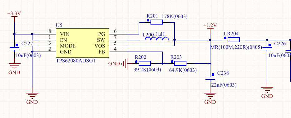
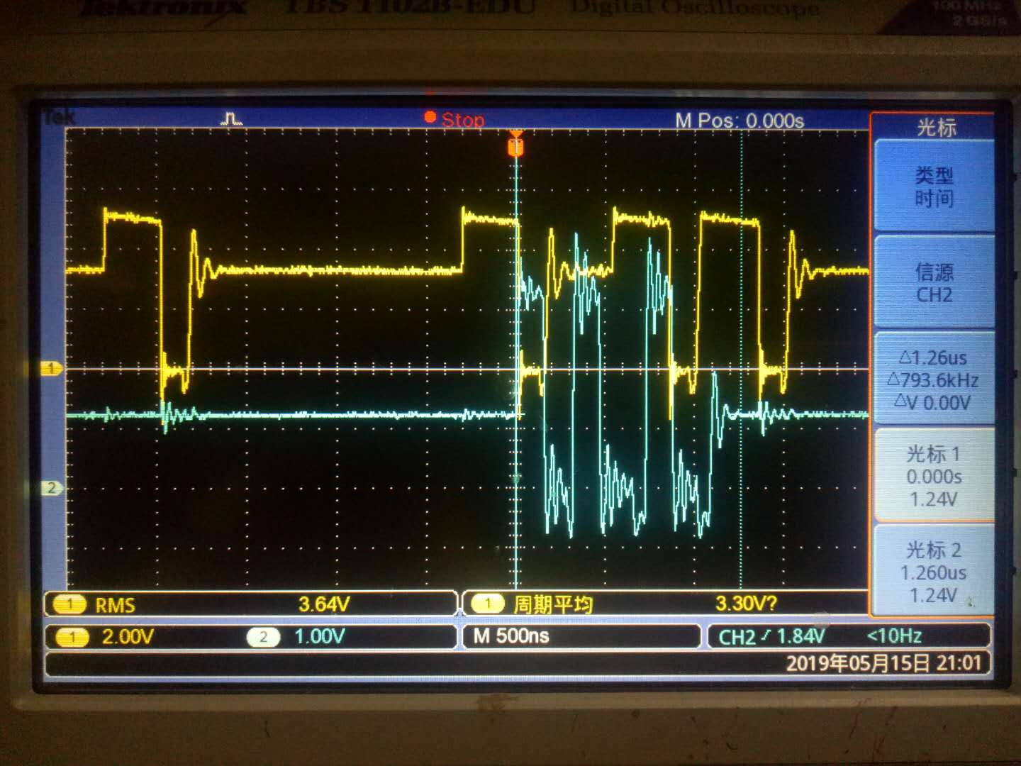
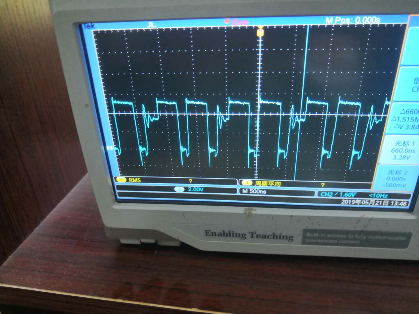
We have a 5V DC power supply on our board. Then we use the power chip of TPS62162DSGT to generate 3.3V. Using the generated 3.3V generates 1.2V by TPS62080ADSGT, then the generated 3.3V and 1.2V to give Power supply for TMS320F28377D DSP, as a result, we found that the DSP always entered the low-power mode during the test. Therefore, the power chip was carefully tested and found that the voltage generated by the two power chip filters was correct, but the waveform of the chopped output was not Correct (as shown in the attached file), by checking the data sheet, it is found that the TPS62080ADSGT will enter the Snooze Mode, and the TPS62162DSGT will enter the Power Good mode. Excuse me, what is the reason for the abnormality? However, this power supply circuit is designed according to the manual of LAUNCHXL-F28379D. One of the boards in the designed design can work normally, but there are problems with two boards, so I don't know where the problem is. We measured the output waveform of 3. 3V separately by changing the size of the 3. 3V load. However, the TPS62162DSGT always runs the Power Good mode, and does not run in the PWM mode. The load varies from 20R to 100R. The waveform is shown in the attached file.

-
Ask a related question
What is a related question?A related question is a question created from another question. When the related question is created, it will be automatically linked to the original question.


