This thread has been locked.

If you have a related question, please click the "Ask a related question" button in the top right corner. The newly created question will be automatically linked to this question.

TMDSCNCD28027: Failure to toggle EPWM output (two consecutive pulses of same polarity)

Part Number: TMDSCNCD28027

I am having issues with the output of EPWM1 of the F28027 control card set up to toggle the output, as follows:

EPwm1Regs.AQCTLA.bit.ZRO = 0x3; // when counter = zero toggles EPWM1A output

The problem is shown below.  The yellow trace is EPWM1A and the blue is EPWM1B.  Two consecutive pulses of EPWM1A are captures in this single-shot trace.  (The pink trace is EPWM4, used to generate ISR and ramp start timings).

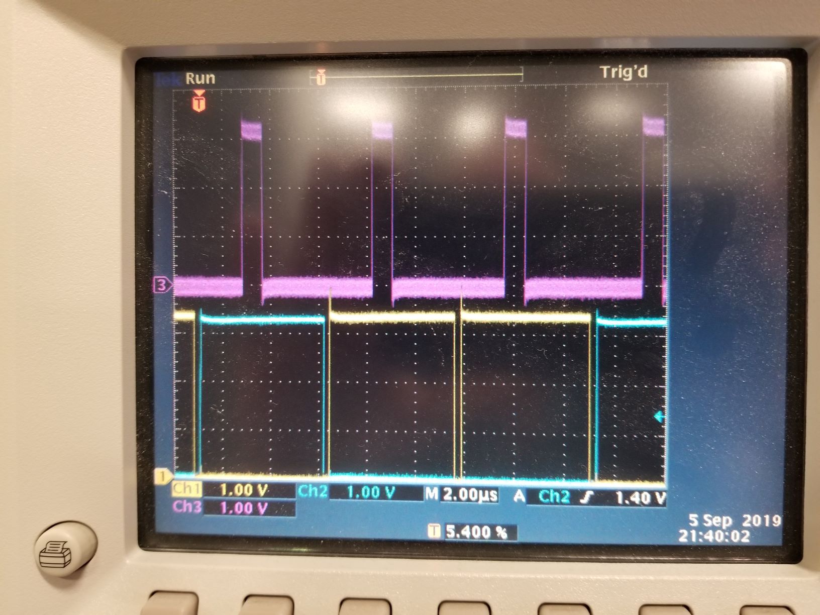
I have EPWM1 set up so a comparator can generate a sync event that loads the TBPHS value (=0) into the time base register.  If the comparator doesn't trip then EPWM1 resets at the value MAX_PERIOD.  The double pulsing occurs when the comparator trips just before MAX_PERIOD, so that the comparator sync is coincident or almost coincident with MAX_PERIOD.  The waveforms shown here are being generated with DC voltages to the comparator inputs, and there is no switching electronics being controlled by the EPWM outputs.


Is there any way to suppress this double pulsing?  This behavior would be disastrous if I actually had the switching electronics hooked up to the controller.

Here is the relevant code:

EALLOW;
// Configure ePWM1AB (used to switch primary half-bridge FETs)
PWM_ComplPairDB_CNF(1, MAX_PERIOD, 1, 0); // configures EPWM1 with complementary outputs, 1=master mode, 0=phase
EPwm1Regs.TBCTL.bit.SYNCOSEL = TB_CTR_ZERO; // sync output when counter = 0
EPwm1Regs.TBCTL.bit.PHSEN = 1; // enable loading counter register from phase register
EPwm1Regs.TBPHS.half.TBPHS = 0; // phase register value
EPwm1Regs.TBCTL.bit.PHSEN = 0x1; //Causes counter to become TBPHS at sync
EPwm1Regs.TBPHS.half.TBPHS = 0x0; // Set counter to 0 at sync
EPwm1Regs.DCTRIPSEL.bit.DCAHCOMPSEL = DC_COMP1OUT; // 8 = DCAH = Comparator 1 output initially (alternates between Comp1 and Comp2 each phase)
EPwm1Regs.TZDCSEL.bit.DCAEVT1 = TZ_DCAH_HI; // 2 = DCAEVT1 set on DCAH high(will become active as Comparator output goes high)
EPwm1Regs.DCACTL.bit.EVT1SRCSEL = 1; // 1 = Source Is DCEVTFILT Signal (filtered by event window, see below)
// EPwm1Regs.DCACTL.bit.EVT1FRCSYNCSEL = 0; // 0 = SYNC path for DCAEVT1.force
EPwm1Regs.DCACTL.bit.EVT1SYNCE = 0x1; // 1 = SYNC Generation Enabled
EPwm1Regs.TZCTL.bit.DCAEVT1 = 0x3; // Do nothing on EPWM1A output on event
EPwm1Regs.DCFCTL.bit.SRCSEL = DC_SRC_DCAEVT1; // 0 = Filter source = DCAEVT1
EPwm1Regs.DCFCTL.bit.PULSESEL = DC_PULSESEL_ZERO; // 1 = Filter start on TBCTR = ZERO
EPwm1Regs.DCFCTL.bit.BLANKE = DC_BLANK_ENABLE; // 1= Enable Blanking window
EPwm1Regs.DCFCTL.bit.BLANKINV = 0; // 0 = Blanking window not inverted
EPwm1Regs.DCFOFFSET = 0; // Filter offset
EPwm1Regs.DCFWINDOW = MIN_PERIOD; // blanking ends just after ramp is triggered
EPwm1Regs.AQCTLA.bit.ZRO = 0x3; // when counter = zero toggles EPWM1A output
EPwm1Regs.AQCTLA.bit.CAU = 0x0; // Do nothing (action disabled)
EPwm1Regs.AQCTLA.bit.PRD = 0x0; // Do nothing (action disabled)
PWM_ComplPairDB_UpdateDB(1, RED, FED); // sets the deadband timing

// Configure PWM2A
PWM_1ch_UpCntDB_Compl_CNF(2, MAX_PERIOD, 0, 0); // changed period to MAX_PERIOD
PWM_1ch_UpCntDB_Compl_UpdateDB(2, REM1, FEM1);

// Configure PWM3A
PWM_1ch_UpCntDB_CNF(3, MAX_PERIOD, 0, 0); // changed period to MAX_PERIOD
PWM_1ch_UpCntDB_UpdateDB(3, REM2, FEM2);

// Configure EPWM4
PWM_1ch_CNF(4, MAX_PERIOD, 0, MIN_PERIOD+MIN_DELTA); // changed to slave and period to MAX_PERIOD
// EPwm4Regs.CMPCTL.bit.SHDWAMODE = 1; // Immediate mode. Only the active compare A register is used.
EPwm4Regs.CMPA.half.CMPA = MAX_PERIOD-50; // Sets EPWM4 output pulse start and trigger point for CNTL_ISR
EPwm4Regs.AQCTLA.bit.ZRO = 0x1; // output low
EPwm4Regs.AQCTLA.bit.CAU = 0x2; // output high
EPwm4Regs.AQCTLA.bit.PRD = 0x0; //Do nothing (action disabled)

// Configure the comparator and ramp generator block
DacDrvCnf(1, 0x7FFF, 1, 4, Slope); //ADDED FOR PQMC: Comp1, DACVAL=max Q15, DACSOURCE=rampgen=1, RAMPSOURCE=PWM4
Comp1Regs.COMPCTL.bit.SYNCSEL = 0; // don't filter the comparator output
DacDrvCnf(2, 0x7FFF, 1, 4, Slope); //ADDED FOR PQMC: Comp2, DACVAL=max Q15, DACSOURCE=rampgen=1, RAMPSOURCE=PWM4
Comp2Regs.COMPCTL.bit.SYNCSEL = 0; // don't filter the comparator output

EDIS;

Thanks for the help,

Ciaran

  • More info on the problem:

    Under certain timing conditions it is possible to create an endless stream of repeating EPWM1A high pulses:

    This occurs when the comparator event occurs coincident or slightly after TBCTR=TBPRD.  The blanking window is set when TBCTR=0.  There appears to be a race condition between DCAEVT1 from the comparator and the assertion of the blanking window, and DCAEVT1 is winning.  It gets through before the blanking window is asserted and resets TBCTR again, creating a double toggle of the EPWM output.

    Is there a configuration solution to this condition, or do I have to give up on using the controller in toggle mode?  Right now I am using two EPWMs for this function (one to control the PWM output and one to generate timing signals).  It might take 4 EPWMs if I separate the control of each switching phase.

  • I did not have time to fully answer your post today, I will reply tomorrow.

    Regards,
    Cody 

  • Thanks, I could use the help on this one.

  • Ciaran,

    It is a little unclear to me how you are using the comparator output to load TBPHS to the TBCTR, can you elaborate?

    On C2000 devices there is a 3 cycle delay before the Blanking Window(BW) takes affect. If you have your BW setup to blank at TBCTR=0 then it will actually start blanking at TBCTR=3, do you think this explains the issue you are seeing?

    To avoid this start the BW at TBPRD-3 cycles, it will continue into the next PWM period.

    Hope it helps.

    Regards,
    Cody 

  • Cody,

    It works!  Woo-hoo!  That 3 cycle delay is consistent with my observations, that there was a little window before the blanking window was active that was letting a second sync pulse through.  I fixed it like you suggested, by changing DCFOFFSET from 0 to MAX_PERIOD-3, then extending the width of the blanking window by 3 to compensate.

    Is there a document that describes these internal delays?  These delays are not shown in the TMS320F2802x,TMS320F2802xx Piccolo Technical Reference Manual (SPRUI09).  For example, "Figure 3-51. Blanking Window Timing Diagram" shows the blanking window starting on the clock after CTR=0 is asserted.  It doesn't show the 3 cycle delay.  I searched all instances of "blanking" in the text and did not find any mention of it.   I see examples of these internal delays elsewhere = for example the PWM configuration code such as PWM_1ch_Cnf.c add 2 to the TBPHS value to compensate for logic delays.  For critical timing it's necessary to know about these delays.

    >> It is a little unclear to me how you are using the comparator output to load TBPHS to the TBCTR, can you elaborate?

    The COMP1 output trips event DCAEVT1, which is set up to generate a sync pulse that resets TBCTR to TBPHS.  DCAEVT1 is filtered by the blanking window to prevent it from syncing the EPWM until MIN_PERIOD has passed.  The relevant settings are:

    EPwm1Regs.DCTRIPSEL.bit.DCAHCOMPSEL = 8; // Set DCAH to COMP1 output
    EPwm1Regs.TZDCSEL.bit.DCAEVT1 = 2; // Set event DCAEVT1 on DCAH high (when COMP1 output goes high)
    EPwm1Regs.DCACTL.bit.EVT1SYNCE = 1; // Enable SYNC generation on event DCAEVT1 (syncs TBCTR to TBPHS)
    EPwm1Regs.TZCTL.bit.DCAEVT1 = 3; // DCAEVT1 has no direct effect on EPWM1a output
    EPwm1Regs.DCACTL.bit.EVT1SRCSEL = 1; // Enable blanking window
    EPwm1Regs.DCFCTL.bit.SRCSEL = 0; // Filter DCAEVT1 event
    EPwm1Regs.DCFCTL.bit.PULSESEL = 1; // Start filter on TBCTR = 0
    EPwm1Regs.DCFCTL.bit.BLANKE = 1; // Enable Blanking window
    EPwm1Regs.DCFCTL.bit.BLANKINV = 0; // Blanking window not inverted
    EPwm1Regs.DCFOFFSET = MAX_PERIOD-3; // Set filter offset to TBPRD-3 to compensate for 3 clock delay to start blanking window (wraps to next cycle)
    EPwm1Regs.DCFWINDOW = MIN_PERIOD+3; // Blanking window duration = MIN_CYCLE, plus 3 to compensate for starting window 3 clocks early.

    Thanks for the help,

    Ciaran

  • Ciaran,

    this will be going into the documentation soon, it was a relatively new finding as most systems designers have assumed that this was part of the delay between the comparator and the trip action.

    Glad that you got this resolved!

    Regards,
    Cody 

  • I want to add a postscript to this issue.

    Actually, as it turns out, the solution mentioned above doesn't solve the problem.  Well, it solved the immediate problem of the comparator tripping shortly after TBPRD, in the 3 clocks before the blanking window is active.  This generates two EPWM sync events, causing the double pulsing issue shown above.  But, it messes up my timing elsewhere.

    The reason it doesn't work is that this is a variable frequency controller, with the frequency determined by comparator trips responding to external analog voltages.  Setting EPwm1Regs.DCFOFFSET = MAX_PERIOD-3 doesn't work because most of the time the period is less than MAX_PERIOD.  Therefore this results in the blanking window occurring at the wrong time when the period length is set by the comparators.

    In other words, we don't know at the beginning of the period how long it will be.  In addition, this technique actually sets the offset for the following period, not the one that just started.  If the blanking window does not start coincident with TBCTR=0, there is no way to prevent double syncing of the counter.

    This appears to me to be a fundamental limitation of this hardware.  I am exploring a more complex scheme that does not rely on toggling.  Each phase is controlled with a separate EPWM and each EPWM turns definitely off or on at specific events.  This requires looping the SYNCO pin back to the SYNCI pin externally so the PWMs can sync each other in a circle.   In the meantime I am using these mitigations:

    1) Operate in a parameter space (RAMPMAXREF, RAMPDECVAL, input voltages, and max_period) where the problem does not occur.
    2) Generate an external pulse on EPWM2 shortly before the MAX_PERIOD to force an external trigger of the comparator
    (force comparator input high using external circuitry).

    Thanks,

    Ciaran

  • Ciaran,

    Ah, with VFD tripped by the PWM that would be a larger issue.

    Are you maintaining a phase offset between your PWMs? What if you reset your TBCTR = -3 and immediately start your blanking at the same value. ie. load TBPHS = -3, this may allow a trip to happen, but it would not take affect for an entire period, at most 3 cycles.

    I agree that this does cause a rather large issue for your system, but we might be able to find a workaround.

    Regards,
    Cody 

  • Cody,

    I didn't know you could use negative values for TBCTR or TBPHS.

    I don't think your suggestion works exactly, but it does point to a possible solution.  The goal is to make sure that the filter starts 3 cycles before the EPWM outputs toggle, to prevent a double toggle of the outputs.

    The start of the filter is set by:

    EPwm1Regs.DCFCTL.bit.PULSESEL = 1; // 1 = Filter start on TBCTR = 0

    The choices are limited to 0 or TBPRD, so the start of the filter is fixed.  But maybe the toggle of the EPWM outputs can be delayed.  I toggle the outputs at TBCTR=0 as so:

    EPwm1Regs.AQCTLA.bit.ZRO = 3; // 3 = when counter = zero toggles EPWM1A output

    But I can delay this for 3 cycles using CMPA, doing nothing at TBCTR=0, and using CMPA to control the toggle:

    EPwm1Regs.CMPA.half.CMPA = 3; // COMPA trigger point (to toggle output after 3 clocks)
    EPwm1Regs.AQCTLA.bit.ZRO = 0; // 0 = Do nothing at TBCTR=0 (action disabled)
    EPwm1Regs.AQCTLA.bit.CAU = 3; // 3 = toggles EPWM1A output at TBCTR=CMPA

    This delays the toggling of the EPWM1 outputs for 3 clocks relative to the start of the blanking window.  It seems to work to prevent double toggling.  It might allow for some jitter, because the comparator can still reset TBCTR to zero a second time in that 3 clock window.  But it seems to be negligible on the scope.

    Thanks for the help,

    Ciaran