Other Parts Discussed in Thread: C2000WARE
Tool/software: TI C/C++ Compiler
Hi,
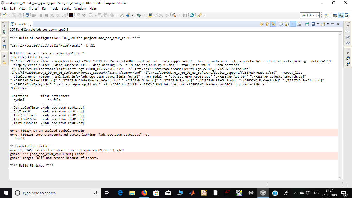
When I am trying to build adc_soc_epwm example, I am getting compilation failure. However other examples are running fine. I have attached my console log and code files.
My Code:
//
// Included Files
//
#include "F28x_Project.h"
#include "math.h"
//
// Defines
//
#define DACA 1
#define DACB 2
#define DACC 3
#define CPUFREQ_MHZ 100
#define REFERENCE 1
//
// Globals
//
volatile struct DAC_REGS* DAC_PTR[4] = {0x0,&DacaRegs,&DacbRegs,&DaccRegs};
Uint32 samplingFreq_hz = 100000;
float PI = 3.14159265359;
unsigned int m = 0;
float nor_sinp = 0;
float nor_sinn = 0;
float fundaFreq_hz = 50;
//
// Function Prototypes
//
void configureDAC(void);
void InitEPwm1Example(void);
void InitEPwm2Example(void);
interrupt void cpu_timer0_isr(void);
//
// Main
//
void main(void)
{
//
// Initialize System Control:
// PLL, WatchDog, enable Peripheral Clocks
// This example function is found in the F2837xD_SysCtrl.c file.
//
InitSysCtrl();
//
// Disable CPU interrupts
//
DINT;
// enable PWM1
CpuSysRegs.PCLKCR2.bit.EPWM1=1;
//
// For this case just init GPIO pins for ePWM1, ePWM2, ePWM3
// These functions are in the F2837xD_EPwm.c file
//
InitEPwm1Gpio();
InitEPwm2Gpio();
//
// Initialize the PIE control registers to their default state.
// The default state is all PIE interrupts disabled and flags are cleared.
// This function is found in the F2837xD_PieCtrl.c file.
//
InitPieCtrl();
//
// Clear all interrupts and initialize PIE vector table:
//
IER = 0x0000;
IFR = 0x0000;
InitPieVectTable();
//
// Configure DAC
//
configureDAC();
//
// Initialize EPWM1
//
InitEPwm1Example();
InitEPwm2Example();
//
// Initialize the Device Peripherals:
//
EALLOW;
CpuSysRegs.PCLKCR0.bit.TBCLKSYNC =0;
ClkCfgRegs.PERCLKDIVSEL.bit.EPWMCLKDIV = 0;
EDIS;
EALLOW;
CpuSysRegs.PCLKCR0.bit.TBCLKSYNC =1;
EDIS;
//
// Map Cpu Timer0 interrupt function to the PIE vector table
//
EALLOW;
PieVectTable.TIMER0_INT = &cpu_timer0_isr;
EDIS;
//
// Initialize Cpu Timers
//
InitCpuTimers();
//
// Configure Cpu Timer0 to interrupt at specified sampling frequency
//
ConfigCpuTimer(&CpuTimer0, CPUFREQ_MHZ, 1000000.0/samplingFreq_hz);
//
// Start Cpu Timer0
//
CpuTimer0Regs.TCR.all = 0x4000;
//
// Enable interrupt
//
IER |= M_INT1;
PieCtrlRegs.PIEIER1.bit.INTx7 = 1;
EINT;
ERTM;
while(1)
{
asm (" NOP");
}
}
//
// configureDAC - Enable and configure the requested DAC module
//
void configureDAC()
{
EALLOW;
DAC_PTR[DACA]->DACCTL.bit.DACREFSEL = REFERENCE;
DAC_PTR[DACA]->DACOUTEN.bit.DACOUTEN = 1;
DAC_PTR[DACA]->DACVALS.all = 0;
DAC_PTR[DACB]->DACCTL.bit.DACREFSEL = REFERENCE;
DAC_PTR[DACB]->DACOUTEN.bit.DACOUTEN = 1;
DAC_PTR[DACB]->DACVALS.all = 0;
DELAY_US(10); // Delay for buffered DAC to power up
EDIS;
}
//CPU timer interupt
interrupt void cpu_timer0_isr(void)
{
//
// Start Cpu Timer1 to indicate begin of interrupt
//
CpuTimer1Regs.TCR.all = 0x0000;
// Generating Sin Wave
//Your Code here for generating sine wave and updating CMPA
//
// Acknowledge this interrupt to receive more interrupts from group 1
//
PieCtrlRegs.PIEACK.all = PIEACK_GROUP1;
//
// Stop Cpu Timer1 to indicate end of interrupt
//
CpuTimer1Regs.TCR.all = 0x0010;
//
// Reload Cpu Timer1
//
CpuTimer1Regs.TCR.all = 0x0030;
}
void InitEPwm1Example()
{
EPwm1Regs.TBPRD = 50000; // Set timer period
EPwm1Regs.TBPHS.bit.TBPHS = 0x0000; // Phase is 0
EPwm1Regs.TBCTR = 0x0000; // Clear counter
//
// Setup TBCLK
//
EPwm1Regs.TBCTL.bit.CTRMODE = TB_COUNT_UPDOWN; // Count mode select
EPwm1Regs.TBCTL.bit.PHSEN = TB_DISABLE; // Disable phase loading
EPwm1Regs.TBCTL.bit.HSPCLKDIV = TB_DIV1; // Clock ratio to SYSCLKOUT
EPwm1Regs.TBCTL.bit.CLKDIV = TB_DIV1;
EPwm1Regs.CMPCTL.bit.SHDWAMODE = CC_SHADOW; // Load registers every ZERO
EPwm1Regs.CMPCTL.bit.SHDWBMODE = CC_SHADOW;
EPwm1Regs.CMPCTL.bit.LOADAMODE = CC_CTR_ZERO;
EPwm1Regs.CMPCTL.bit.LOADBMODE = CC_CTR_ZERO;
//
// Set actions
//
EPwm1Regs.AQCTLA.bit.CAU = AQ_SET; // Action when CTR = CMPA on UP Count (EPWM-A)
EPwm1Regs.AQCTLA.bit.CAD = AQ_CLEAR; // Action when CTR = CMPA on DOWN Count (EPWM-A)
// EPwm1Regs.AQCTLA.bit.PRD = AQ_SET; // Action when CTR = PRD (EPWM-A)
// EPwm1Regs.AQCTLA.bit.ZRO = AQ_CLEAR; // Action when CTR = ZRO (EPWM-A)
EPwm1Regs.AQCTLB.bit.CAU = AQ_SET; // Action when CTR = CMPA on UP Count (EPWM-B)
EPwm1Regs.AQCTLB.bit.CAD = AQ_CLEAR; // Action when CTR = CMPA on DOWN Count (EPWM-B)
// EPwm1Regs.AQCTLB.bit.PRD = AQ_SET; // Action when CTR = PRD (EPWM-B)
// EPwm1Regs.AQCTLB.bit.ZRO = AQ_CLEAR; // Action when CTR = ZRO (EPWM-B)
//
// Active Low PWMs - Setup Deadband
//
EPwm1Regs.DBCTL.bit.OUT_MODE = DB_FULL_ENABLE; // Enable Deadband Out Mode
EPwm1Regs.DBCTL.bit.POLSEL = DB_ACTV_HIC; // Deadband Polarity Select
EPwm1Regs.DBCTL.bit.IN_MODE = DBA_ALL; // Enable Deadband IN Mode
EPwm1Regs.DBRED.bit.DBRED = 2*100; // Rising Edge Dead Band
EPwm1Regs.DBFED.bit.DBFED = 2*100; // Falling Edge Dead Band
}
void InitEPwm2Example()
{
EPwm2Regs.TBPRD = 50000; // Set timer period
EPwm2Regs.TBPHS.bit.TBPHS = 0x0000; // Phase is 0
EPwm2Regs.TBCTR = 0x0000; // Clear counter
//
// Setup TBCLK
//
EPwm2Regs.TBCTL.bit.CTRMODE = TB_COUNT_UPDOWN; // Count mode select
EPwm2Regs.TBCTL.bit.PHSEN = TB_DISABLE; // Disable phase loading
EPwm2Regs.TBCTL.bit.HSPCLKDIV = TB_DIV1; // Clock ratio to SYSCLKOUT
EPwm2Regs.TBCTL.bit.CLKDIV = TB_DIV1;
EPwm2Regs.CMPCTL.bit.SHDWAMODE = CC_SHADOW; // Load registers every ZERO
EPwm2Regs.CMPCTL.bit.SHDWBMODE = CC_SHADOW;
EPwm2Regs.CMPCTL.bit.LOADAMODE = CC_CTR_ZERO;
EPwm2Regs.CMPCTL.bit.LOADBMODE = CC_CTR_ZERO;
//
// Set actions
//
EPwm2Regs.AQCTLA.bit.CAU = AQ_SET; // Action when CTR = CMPA on UP Count (EPWM-A)
EPwm2Regs.AQCTLA.bit.CAD = AQ_CLEAR; // Action when CTR = CMPA on DOWN Count (EPWM-A)
// EPwm2Regs.AQCTLA.bit.PRD = AQ_SET; // Action when CTR = PRD (EPWM-A)
// EPwm2Regs.AQCTLA.bit.ZRO = AQ_CLEAR; // Action when CTR = ZRO (EPWM-A)
EPwm2Regs.AQCTLB.bit.CAU = AQ_SET; // Action when CTR = CMPA on UP Count (EPWM-B)
EPwm2Regs.AQCTLB.bit.CAD = AQ_CLEAR; // Action when CTR = CMPA on DOWN Count (EPWM-B)
// EPwm2Regs.AQCTLB.bit.PRD = AQ_SET; // Action when CTR = PRD (EPWM-B)
// EPwm2Regs.AQCTLB.bit.ZRO = AQ_CLEAR; // Action when CTR = ZRO (EPWM-B)
//
// Active Low PWMs - Setup Deadband
//
EPwm2Regs.DBCTL.bit.OUT_MODE = DB_FULL_ENABLE; // Enable Deadband Out Mode
EPwm2Regs.DBCTL.bit.POLSEL = DB_ACTV_HIC; // Deadband Polarity Select
EPwm2Regs.DBCTL.bit.IN_MODE = DBA_ALL; // Enable Deadband IN Mode
EPwm2Regs.DBRED.bit.DBRED = 2*100; // Rising Edge Dead Band
EPwm2Regs.DBFED.bit.DBFED = 2*100; // Falling Edge Dead Band
}
//
// End of file
//