This thread has been locked.

If you have a related question, please click the "Ask a related question" button in the top right corner. The newly created question will be automatically linked to this question.

CCS/F28M35H52C: Part number of the docking station (R3)

Part Number: F28M35H52C
Other Parts Discussed in Thread: TMDSDOCKH52C1, CONTROLSUITE

Tool/software: Code Composer Studio

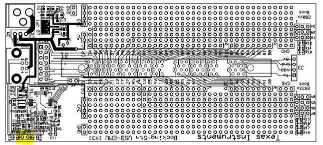
I bought TMDSDOCKH52C1 package including a TMS320F28M35H52C controlCard (release 2.0) and a docking station (R3).  I tried to use an external emulator XDS200 plugged in the port J2 of the docking station but the package does not provide the 5VDC adapter for the port JP1.  Where can I find and order the 5VDC adapter?  I asked the question is because this connector is 2.5mm ID and 6.5mm OD.  Thanks.

Yong

  • Hi Yong,

    It should be 2.5mm ID & 5.5mm OD, based on the barrel connector listed in the Docking Station's BOM. 

    A compatible supply could then be the: Phihong PSAC05R-050(P)-R-C2 & a Phihong RPBAG.

    Note that instead of using an external supply, you can use a USB cable plugged into the Docking Station to provide the 5V power.  If you want to enable your xds200 to be the emulator & remove any chance of contention with the onboard emulator, you can populate J8 on the Docking Station baseboard.

    Hopefully this helps!


    Thank you,
    Brett

  • Hello, Brett,

       Thank you very much for your email and the part number.

       Yes, I indeed want to use xds200 emulator but I cannot find J8 from the docking station baseboard.  Do you mean to populate J84/J85/J86/J7?  In addition, should I populate R40 - R46 of the F28M35xx controlCard?

       Thanks,

       Yong

  • Hi Yong,

    J8 on the Docking Station is highlighted below.  You can find the schematic & pcb files for this hardware within controlSUITE.


    I'll look into your question on the controlCARD's R40-46, shortly.


    Thank you,
    Brett

  • Hi Yong,

    The schematic for the Controlcard is in the below directory if you have not already found it:

    C:\ti\controlSUITE\development_kits\~controlCARDs\CCF28M35xxHWdevPkg_v3\R_PWB_RevD

    Yes, you'll need to populate R40 - R46 to connect the F28M35 to the JTAG header on the docking station.

    Best,

    Kevin

  • Hello, Brett,

       Thank you for your email and I populate J8 of the Docking Station baseboard and R40-R46 of the F28M3xx controlCard.  I run Test Connection and get following error message,

    [Start: Texas Instruments XDS2xx USB Debug Probe_0]

    Execute the command:

    %ccs_base%/common/uscif/dbgjtag -f %boarddatafile% -rv -o -S integrity

    [Result]


    -----[Print the board config pathname(s)]------------------------------------

    C:\Users\zhouyo\AppData\Local\TEXASI~1\CCS\
    ccs910\0\0\BrdDat\testBoard.dat

    -----[Print the reset-command software log-file]-----------------------------

    This utility has selected a 560/2xx-class product.
    This utility will load the program 'xds2xxu.out'.
    The library build date was 'Jun 3 2019'.
    The library build time was '14:44:57'.
    The library package version is '8.2.0.00004'.
    The library component version is '35.35.0.0'.
    The controller does not use a programmable FPGA.
    The controller has a version number of '13' (0x0000000d).
    The controller has an insertion length of '0' (0x00000000).
    This utility will attempt to reset the controller.
    This utility has successfully reset the controller.

    -----[Print the reset-command hardware log-file]-----------------------------

    This emulator does not create a reset log-file.

    -----[An error has occurred and this utility has aborted]--------------------

    This error is generated by TI's USCIF driver or utilities.

    The value is '-233' (0xffffff17).
    The title is 'SC_ERR_PATH_BROKEN'.

    The explanation is:
    The JTAG IR and DR scan-paths cannot circulate bits, they may be broken.
    An attempt to scan the JTAG scan-path has failed.
    The target's JTAG scan-path appears to be broken
    with a stuck-at-ones or stuck-at-zero fault.

    [End: Texas Instruments XDS2xx USB Debug Probe_0]

      Yong

  • Hello, Kevin,

       Thank you for your suggestion.  I populate the R40-R46 of the controlCard and J8 of the Docking Station baseboard and run Test Connection but get following error message:

    [Start: Texas Instruments XDS2xx USB Debug Probe_0]

    Execute the command:

    %ccs_base%/common/uscif/dbgjtag -f %boarddatafile% -rv -o -S integrity

    [Result]


    -----[Print the board config pathname(s)]------------------------------------

    C:\Users\zhouyo\AppData\Local\TEXASI~1\CCS\
    ccs910\0\0\BrdDat\testBoard.dat

    -----[Print the reset-command software log-file]-----------------------------

    This utility has selected a 560/2xx-class product.
    This utility will load the program 'xds2xxu.out'.
    The library build date was 'Jun 3 2019'.
    The library build time was '14:44:57'.
    The library package version is '8.2.0.00004'.
    The library component version is '35.35.0.0'.
    The controller does not use a programmable FPGA.
    The controller has a version number of '13' (0x0000000d).
    The controller has an insertion length of '0' (0x00000000).
    This utility will attempt to reset the controller.
    This utility has successfully reset the controller.

    -----[Print the reset-command hardware log-file]-----------------------------

    This emulator does not create a reset log-file.

    -----[An error has occurred and this utility has aborted]--------------------

    This error is generated by TI's USCIF driver or utilities.

    The value is '-233' (0xffffff17).
    The title is 'SC_ERR_PATH_BROKEN'.

    The explanation is:
    The JTAG IR and DR scan-paths cannot circulate bits, they may be broken.
    An attempt to scan the JTAG scan-path has failed.
    The target's JTAG scan-path appears to be broken
    with a stuck-at-ones or stuck-at-zero fault.

    [End: Texas Instruments XDS2xx USB Debug Probe_0]

      In addition, from the link of 

    https://e2e.ti.com/support/microcontrollers/c2000/f/171/t/344517?How-to-connect-the-F28M35-controlcard-via-docking-JTAG-

      It looks like even the package has 3 emulators (built-in emulator on controlCard (J20), built-in emulator on Docking Station baseboard JP2, and external emulator on Docking Station baseboard J2), it only makes on board emulator working (J20). To use either emulator JP2 or J2, it needs to remove the isolation chips on the controlCard (U19-U222 and U40) to disable emulator on controlCard J20. Then to populate J8 of Docking Station baseboard to disable emulator JP2 to enable other emulator (could be xds200) J2?  

      Thanks,

      Yong

  • Hi Yong,

    Yong Zhou1 said:
      It looks like even the package has 3 emulators (built-in emulator on controlCard (J20), built-in emulator on Docking Station baseboard JP2, and external emulator on Docking Station baseboard J2)

    Yes, you understand correctly.

    Yong Zhou1 said:
    it only makes on board emulator working (J20)

    When using the XDS200 on the docking station's J2 you don't have the USB cable plugged into the ControlCard J20, correct?

    Yong Zhou1 said:
    To use either emulator JP2 or J2, it needs to remove the isolation chips on the controlCard (U19-U222 and U40) to disable emulator on controlCard J20. 

    You don't need to remove the isolator chips completely, you can just take the 0 ohm resistors off (R48, 49, 50, 51, 52, 53, and 55)  to remove contention on the signals.

    Yong Zhou1 said:
    Then to populate J8 of Docking Station baseboard to disable emulator JP2 to enable other emulator (could be xds200) J2?  

    Populating J8 is needed to turn off the JP2 (U2 FTDI chip) JTAG.

    Best,

    Kevin

  • Hello, Kevin,
       Thank you for answering my questions. Yes, for each emulation, I only plugged in one USB or emulator.  That is
     
      1.  For emulation of controlCard by only plugged in USB on J20 and 5 VDC on docking station JP1;
      2.  For emulation of docking station by only plugged in USB on JP2 and use its 5 VDC for docking station;
      3.  For external emulator xds200 by by only plugged in emulator on J2 and 5 VDC on docking station JP1.
       With populated R40 - R46, 1 is operational (without USB plugged in JP2 of docking station).  However, when testing 2, Test Connection only has 83 % successes repeatedly, is there any comment?
       My understanding is to make use of 3, I have to remove R48, 49, 50, 51, 52, 53, and 55 and populating J8 which seem not convenient to switch back to 1. 
     
        Thanks,
     
        Yong


  • Hi Yong,

    Sorry, didn't mean to click the resolved button. You can ignore or reject that...

    Yong Zhou1 said:
    However, when testing 2, Test Connection only has 83 % successes repeatedly, is there any comment?

    You have J8 not populated in this case, correct? I think J9 on the docking station may also need to be populated.

    Yong Zhou1 said:
     My understanding is to make use of 3, I have to remove R48, 49, 50, 51, 52, 53, and 55 and populating J8 which seem not convenient to switch back to 1. 

    I believe this is needed to remove any contention on the JTAG signals. Another thing you can try before removing all the resistors listed is setting both switches on SW3 to the off state. That may be enough to remove unwanted contention.

    Best,

    Kevin

  • Hello, Kevin,

       Thank you for your suggestion.  To make Test 2 operational, I populated J8 but it is disable the emulator then not working.  Populating J9 had no difference than before with error message "Some of the values were corrupted - 83.3 percent".  Switch off 1 or both 1/2 of SW3 had no differences with the same error message.

       Regards,

       Yong

  • Hi Yong,

    I cannot tell from your last message.  Have you been able to get the system working as you desire (or at least are able to move forward with your evaluation)?

    If things are still not working, could you maybe post some pictures of your setup?  Or describe your current setup that is not working?


    Thank you,
    Brett

  • Hello, Brett,

      It turned out Kevin partially answered my questions. With the package, I can only make built-in emulator of controlCard working but not other two emulators (one is built-in emulator of Docking Station and other is external emulator) without disable emulator of controlCard by removing some resisters.  Even my goal is to use external emulator and evaluate all of three emulators that available, but I gave it up.

      Thanks,

      Yong 

  • Hi Yong,

    First, I'm sorry for the challenges in getting an external emulator working with the F28M35x controlCARD.  On newer devices' controlCARDs we've made using an external emulator easier to evaluate, but it's definitely pretty complex with this controlCARD.

    If you decide to come back to this (and try to get an external emulator working with this hardware/kit), feel free to start up a new thread.  As far as I'm aware, we should be able to get it to work if we're very careful.  However, I completely understand that you may want to prioritize evaluation of the actual C2000 MCU.  :)

    I'm going to go ahead and close this thread & mark it as "TI Thinks Resolved".  This doesn't mean that we've solved your question, but instead that we're not going to work on the thread any more - so don't reject it :).  Good luck on your project!


    Thank you,
    Brett