This thread has been locked.

If you have a related question, please click the "Ask a related question" button in the top right corner. The newly created question will be automatically linked to this question.

TMS320F28067: problems with boost pfc transfer function

Part Number: TMS320F28067

Dear Shamim ,

Thanks for sharing information regarding SPRA902A , we are  still facing  issue in voltage and current loop control regarding taking gains and controller for resistive load i.e power varies from 100W to 1000W

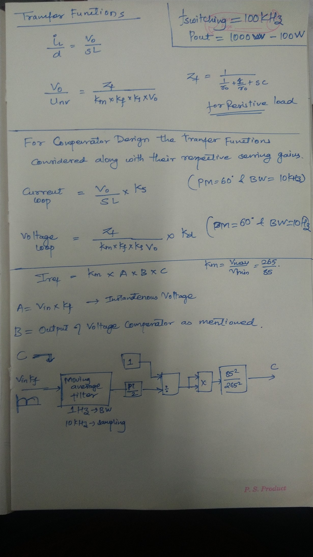
for making compensator we have used the below transfer functions as mentioned in SPRA902A paper also in forum as a typo factor of 2 in voltage loop still we are facing issues.

I have attached below the calculation procedure that we are following . Kindly reply us as soon as possible
  • So what is your question? I am not very clear about your question.

    Shamim

  • We are trying to design Boost PFC (1kW) 100Khz switching frequency using TMS320f28067 for VARIABLE Loading conditions(100W - 1kW) Output Voltage 380 Volts.
    The documents that we have referred are SPRA902A and SPRUI55.
    I also modeled the entire circuit in Matlab for all loops (Input Voltage squared inverse, Current Loop and Voltage Loop).

    For Input Voltage and C-Inverse Calculation we have followed SPRA902A as it says!!
    Only difference is that we are using a digital low pass filter to get Average of Input Voltage and we are scaling it to operate from 265Vrms to 85Vrms.


    Here i have attached the Matlab script for controller  design.

    s = tf('s');

    l = 260e-6;
    c = 660e-6;
    vout = 380;

    vin = 230;
    ro = 144.4; % Full Load

    vmax = 265*1.4142;
    vmin = 85*1.4142;
    voutmax = 600.2;
    Imax = 16.6;

    %% Current Transfer Function
    ctf = vout/(s*l);
    opts = pidtuneOptions('PhaseMargin',60,'DesignFocus','balanced');
    ccomp = pidtune((ctf/Imax),'PI',(2*3.1416*10000),opts);
    ccompz = c2d(ccomp,1/50000,'tustin');


    %% TI Voout to Control transfer function
    vti = (vmin*Imax*ro)/((2+(s*c*ro))*vout);   % Corrected from SPRA902A % removed the typo of 2
    opts = pidtuneOptions('PhaseMargin',60,'DesignFocus','balanced');
    vcomp = pidtune(vti/voutmax,'PI',(2*3.1416*10),opts);
    vcompz = c2d(vcomp,1/10000,'tustin');

    We are facing following issues:
    1. When running at 85 Volts and Full Load (144.4 Ohms/ 1000W) the Inductor Current shape and value is proper but at Lighter Loads(1444Ohms / 100W) it gets distorted.
    2. When Operating at 230 Volts for Both Full Load and Lighter Load the current shape is deformed but value appears to be approximately correct.
    3. Also there is Issue with the value of Zf to be considered from SPRA902A. (For Constant Power Load or Impedance Load)???

    Are we missing out something in Controller Design??
    Are we missing something in Input Voltage Scaling??

    Are we missing something in Understanding??

  • 1. When running at 85 Volts and Full Load (144.4 Ohms/ 1000W) the Inductor Current shape and value is proper but at Lighter Loads(1444Ohms / 100W) it gets distorted.

    That is expected as it can go into DCM mode. Please read PFC related control in literature and you will know more about it.

    No, You are not missing anything. But it seems like you are not aware of loop bandwidth change with operating condition. This is common phenomenon. You can look at current loop bandwidth at this condition and then try to increase the loop gain while maintaining loop stability.

    2. When Operating at 230 Volts for Both Full Load and Lighter Load the current shape is deformed but value appears to be approximately correct.

    Same comment. However, here also need to see your current loop reference waveform. That should be sinusoidal or close to it. Then adjust the loop bandwidth as I explained.

    .3. Also there is Issue with the value of Zf to be considered from SPRA902A. (For Constant Power Load or Impedance Load)??? 

    No, there is no issue with Zf in SPRA902

    Shamim

  • 1. We have kept current loop bandwidth 10kHz for now ,and same controller for all operating conditions (85-265V).

    2. It would be nice if you could tell us the transfer function of current plant in DCM Mode.

    3. Our main doubt is how the current/voltage loop bandwidth is supposed to be changed as per Variable Input Voltage and Variable Loading conditions.

    4. We wanted to know the actual meaning of Load Impedance(Zl) and Output Impedance(Ro).

    5. Also we wanted to know the relation between Bandwidth and the Sampling Frequency for Tustin Transformation.
       (In our case we have used the ADC triggering frequency as 100KHz  while we are using these values for feedback in  Current controller at 50Khz and voltage controller at 10KHz)
        in our case is also ISR frequency (50KHz for Current and 10Khz for Voltage) at which the controller is being executed)
    6. For transforming the continuous to discrete domain , sampling frequency considered is the frequency at which voltage and current controller isr is executed , is it right?
  • Most of these information are available in books and public literature (papers and transactions on Power Electronics). Please review and study those material. 

    4. Load impedance is the impedance of the load that is connected to PFC output. It can be a resistive load, a constant power load or a R-L type of load. Output impedance is the impedance ( looking into the PFC stage) from its output terminals. If you are not familiar with this pls review and study related material available in public

    5. There is no direct relationship. Usually the maximum bandwidth you can achieve in digital system is roughly about 6-8 time lower than the sampling frequency. So with a 50kHz current loop ISR frequency you can get about 8kHz current loop BW .

    6. Yes, that is correct

    Shamim