


Part Number: TMS320F28069
Hello everyone,
My aim for the test is that CLA Task1 and ADC_ISR can be triggered by ADCINT1 at the same time. And then CLA Task1 complete will trigger CLA_ISR.
I am confused about PIEIER1 and PIEIRE10 in PieCtrlRegs.
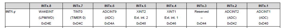
In pie interrupt vector table, I found that ADCINT1 can assign to INT1.1 or INT10.1 in the picture below:
Using INT1.1 can achieve my aim, but replace to INT10.1 will go to ISR_ILLEGAL

The using code as following:
Workable condition:
EALLOW;
PieVectTable.ADCINT1 = &ADC_isr;
PieVectTable.CLA1_INT1 = &Cla1_isr1;
PieCtrlRegs.PIEIER1.bit.INTx1 = 1; //ADCINT1
PieCtrlRegs.PIEIER11.bit.INTx1 = 1; //CLA1_INT1
EDIS;
IER |= M_INT1;
IER |= M_INT11;
EINT;
ERTM;
Unworkable condition:
Replace the code as the following
PieCtrlRegs.PIEIER1.bit.INTx1 = 1; => PieCtrlRegs.PIEIER10.bit.INTx1 = 1;
IER |= M_INT1; => IER |= M_INT10;
( PieCtrlRegs.PIEACK in interrupt replace from 0x0001 to 0x0200 )
Other conditions are the same.
So what may cause to ISR_ILLEAGE. Is there anything I didn't notice?
Thanks.

