This thread has been locked.

If you have a related question, please click the "Ask a related question" button in the top right corner. The newly created question will be automatically linked to this question.

CCS/TMS320F28030: OLIMEX XDS100V3 on CUSTOM BOARD doesnt work

Part Number: TMS320F28030
Other Parts Discussed in Thread: CONTROLSUITE

Tool/software: Code Composer Studio

Hi

I just made my own custom board for TMS320F28030, i follow JTAG 14 standart from Ti and purchase olimex XDS100V3, just trying flashing but it didn't in the CCS Consolr view stated the "CPU just held in reset ..."

but JTAG integrity test have succeed, i had double check my HW connection, just one pin i didn't know, i just left TDIS floating

anyone have experience made custom board with 3rd party JTAG debuggere (Olimex XDS100V3).

Thank you in advance

BR

Abdin

  • Abdin,

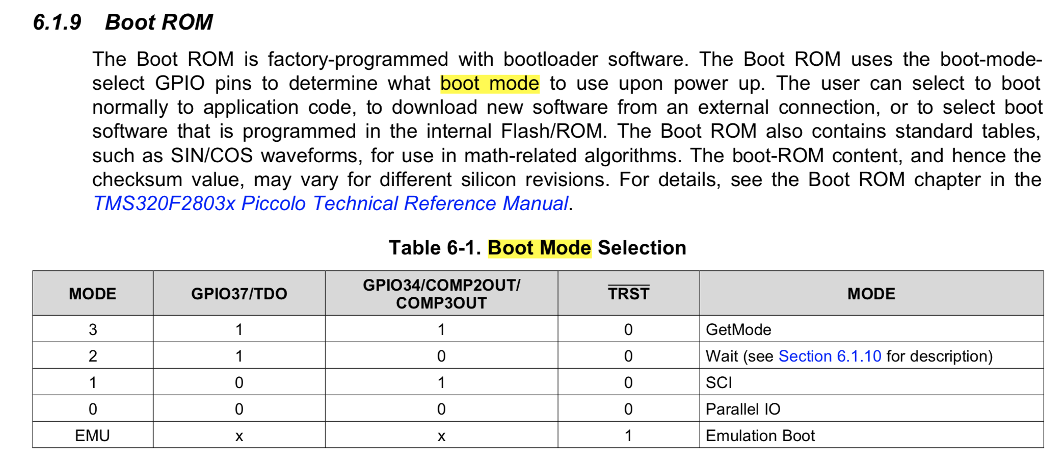
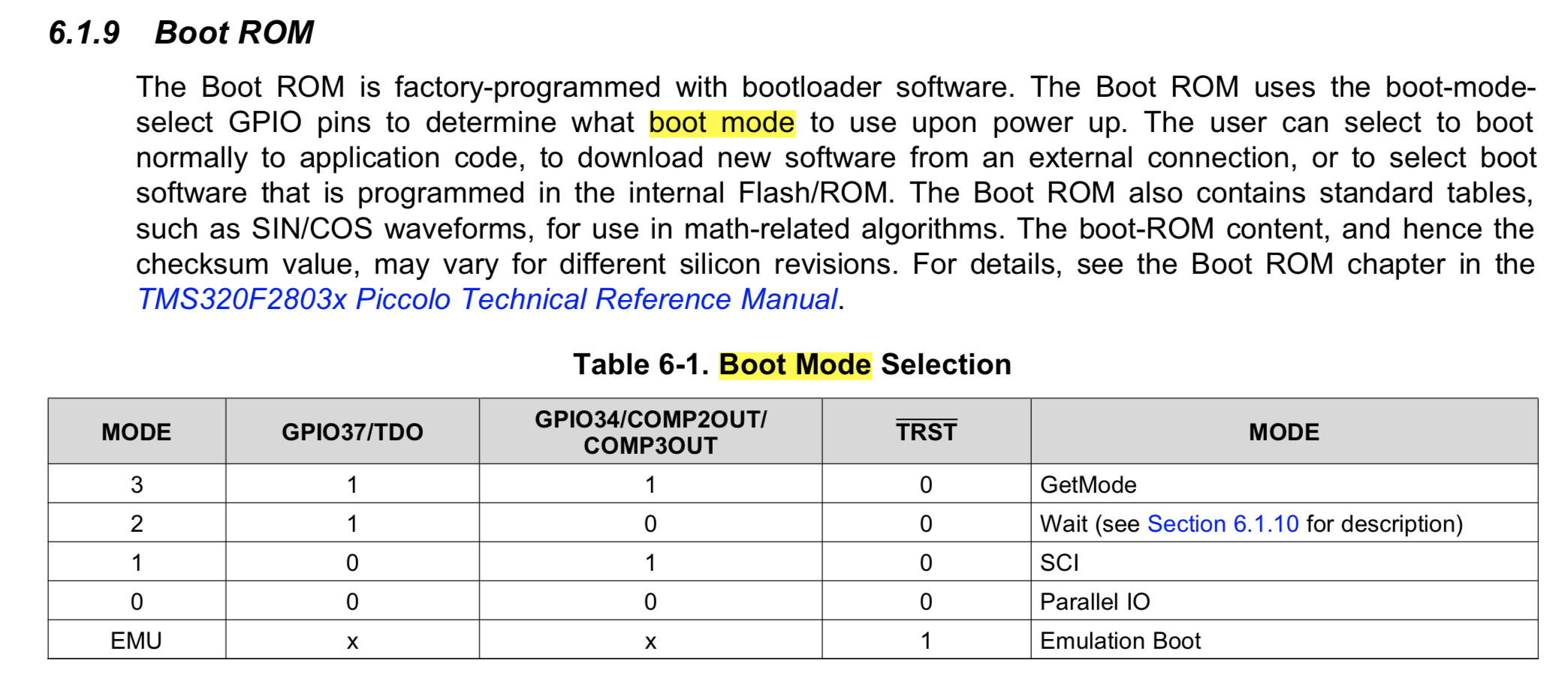
    I would check to see the state of the boot pins; for debug I'd like to get the device in wait boot mode as shown here

    https://www.ti.com/document-viewer/TMS320F28035/datasheet/boot-rom-litsprs230-0453#litSPRS230-0453 

    I would also recommend looking at an app note we have to help debug common JTAG connection issues  https://www.ti.com/lit/spracf0 

    You'll find a flow chart in the above app note, if you could go through those steps and if there is still an issue let me know how far you were able to get it should help the debug.

    Best,

    Matthew

  • Hi Matthew

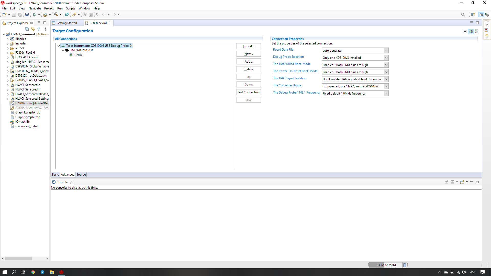
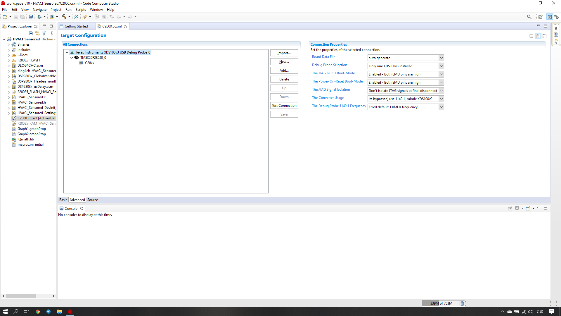
    From Code Composer Studio when I do test connection i have text prompt as shown

    [Start: Texas Instruments XDS100v3 USB Debug Probe_0]

    Execute the command:

    %ccs_base%/common/uscif/dbgjtag -f %boarddatafile% -rv -o -F inform,logfile=yes -S pathlength -S integrity

    [Result]


    -----[Print the board config pathname(s)]------------------------------------

    C:\Users\ENGINEER\AppData\Local\TEXASI~1\
    CCS\ccs1000\0\0\BrdDat\testBoard.dat

    -----[Print the reset-command software log-file]-----------------------------

    This utility has selected a 100- or 510-class product.
    This utility will load the adapter 'jioserdesusbv3.dll'.
    The library build date was 'Feb 13 2020'.
    The library build time was '18:30:11'.
    The library package version is '9.1.0.00001'.
    The library component version is '35.35.0.0'.
    The controller does not use a programmable FPGA.
    The controller has a version number of '4' (0x00000004).
    The controller has an insertion length of '0' (0x00000000).
    This utility will attempt to reset the controller.
    This utility has successfully reset the controller.

    -----[Print the reset-command hardware log-file]-----------------------------

    The scan-path will be reset by toggling the JTAG TRST signal.
    The controller is the FTDI FT2232 with USB interface.
    The link from controller to target is direct (without cable).
    The software is configured for FTDI FT2232 features.
    The controller cannot monitor the value on the EMU[0] pin.
    The controller cannot monitor the value on the EMU[1] pin.
    The controller cannot control the timing on output pins.
    The controller cannot control the timing on input pins.
    The scan-path link-delay has been set to exactly '0' (0x0000).

    -----[The log-file for the JTAG TCLK output generated from the PLL]----------

    Test Size Coord MHz Flag Result Description
    ~~ ~~~~~ ~~~~~~ ~~~~~~~~~ ~~~~~~~~~~~~~~~~~~~
    1 64 - 01 00 500.0kHz O good value measure path length
    2 64 + 00 00 1.000MHz [O] good value apply explicit tclk

    There is no hardware for measuring the JTAG TCLK frequency.

    In the scan-path tests:
    The test length was 2048 bits.
    The JTAG IR length was 38 bits.
    The JTAG DR length was 1 bits.

    The IR/DR scan-path tests used 2 frequencies.
    The IR/DR scan-path tests used 500.0kHz as the initial frequency.
    The IR/DR scan-path tests used 1.000MHz as the highest frequency.
    The IR/DR scan-path tests used 1.000MHz as the final frequency.

    -----[Measure the source and frequency of the final JTAG TCLKR input]--------

    There is no hardware for measuring the JTAG TCLK frequency.

    -----[Perform the standard path-length test on the JTAG IR and DR]-----------

    This path-length test uses blocks of 64 32-bit words.

    The test for the JTAG IR instruction path-length succeeded.
    The JTAG IR instruction path-length is 38 bits.

    The test for the JTAG DR bypass path-length succeeded.
    The JTAG DR bypass path-length is 1 bits.

    -----[Perform the Integrity scan-test on the JTAG IR]------------------------

    This test will use blocks of 64 32-bit words.
    This test will be applied just once.

    Do a test using 0xFFFFFFFF.
    Scan tests: 1, skipped: 0, failed: 0
    Do a test using 0x00000000.
    Scan tests: 2, skipped: 0, failed: 0
    Do a test using 0xFE03E0E2.
    Scan tests: 3, skipped: 0, failed: 0
    Do a test using 0x01FC1F1D.
    Scan tests: 4, skipped: 0, failed: 0
    Do a test using 0x5533CCAA.
    Scan tests: 5, skipped: 0, failed: 0
    Do a test using 0xAACC3355.
    Scan tests: 6, skipped: 0, failed: 0
    All of the values were scanned correctly.

    The JTAG IR Integrity scan-test has succeeded.

    -----[Perform the Integrity scan-test on the JTAG DR]------------------------

    This test will use blocks of 64 32-bit words.
    This test will be applied just once.

    Do a test using 0xFFFFFFFF.
    Scan tests: 1, skipped: 0, failed: 0
    Do a test using 0x00000000.
    Scan tests: 2, skipped: 0, failed: 0
    Do a test using 0xFE03E0E2.
    Scan tests: 3, skipped: 0, failed: 0
    Do a test using 0x01FC1F1D.
    Scan tests: 4, skipped: 0, failed: 0
    Do a test using 0x5533CCAA.
    Scan tests: 5, skipped: 0, failed: 0
    Do a test using 0xAACC3355.
    Scan tests: 6, skipped: 0, failed: 0
    All of the values were scanned correctly.

    The JTAG DR Integrity scan-test has succeeded.

    [End: Texas Instruments XDS100v3 USB Debug Probe_0]

    What does it mean ?

    1. is it the IC just alive so debugger can recognize the JTAG peripheral scan ?

    2. it is can not guarantee that debugger can recognize the CPU state and just have communication with JTAG peripheral only

    when i try to debug or load the program i have text prompt shown :

    C28xx: Failed CPU Reset: (Error -1137 @ 0x6) Device is held in reset. Take the device out of reset, and retry the operation. (Emulation package 9.1.0.00001)
    C28xx: Trouble Reading Register PC: (Error -1137 @ 0x0) Device is held in reset. Take the device out of reset, and retry the operation. (Emulation package 9.1.0.00001)
    C28xx: Trouble Reading Register ST1: (Error -1137 @ 0x6) Device is held in reset. Take the device out of reset, and retry the operation. (Emulation package 9.1.0.00001)
    C28xx: GEL: Error while executing OnReset(-1): Target failed to read register ST1
    at (ST1&~(0x0100)) [f28030.gel:290]
    at C28x_Mode() [f28030.gel:32]
    at OnReset(-(1))
    C28xx: GEL: Error while executing OnTargetConnect(): Reset failed: retcode=-1
    at GEL_Reset() [f28030.gel:94]
    at OnTargetConnect()
    C28xx: Flash Programmer: Warning: The configured device (TMS320F28030), does not match the detected device (). Flash Programming operations could be affected. Please consider modifying your target configuration file.
    C28xx: Failed CPU Reset: (Error -1137 @ 0x0) Device is held in reset. Take the device out of reset, and retry the operation. (Emulation package 9.1.0.00001)
    C28xx: Trouble Reading Register PC: (Error -1137 @ 0x0) Device is held in reset. Take the device out of reset, and retry the operation. (Emulation package 9.1.0.00001)
    C28xx: Trouble Reading Register ST1: (Error -1137 @ 0x6) Device is held in reset. Take the device out of reset, and retry the operation. (Emulation package 9.1.0.00001)
    C28xx: GEL: Error while executing OnReset(-1): Target failed to read register ST1
    at (ST1&~(0x0100)) [f28030.gel:290]
    at C28x_Mode() [f28030.gel:32]
    at OnReset(-(1))
    C28xx: GEL: Error calling OnPreFileLoaded(): Reset failed: retcode=-1
    C28xx: Trouble Writing Memory Block at 0xae0 on Page 1 of Length 0x1: (Error -1137 @ 0xAE1) Device is held in reset. Take the device out of reset, and retry the operation. (Emulation package 9.1.0.00001)
    C28xx: Error occurred during flash operation: Target failed to write 0x00000AE0@Data
    C28xx: Trouble Writing Memory Block at 0xae1 on Page 1 of Length 0x1: (Error -1137 @ 0xAE2) Device is held in reset. Take the device out of reset, and retry the operation. (Emulation package 9.1.0.00001)
    C28xx: Error occurred during flash operation: Target failed to write 0x00000AE1@Data
    C28xx: Trouble Writing Memory Block at 0xae2 on Page 1 of Length 0x1: (Error -1137 @ 0xAE3) Device is held in reset. Take the device out of reset, and retry the operation. (Emulation package 9.1.0.00001)
    C28xx: Error occurred during flash operation: Target failed to write 0x00000AE2@Data
    C28xx: Trouble Writing Memory Block at 0xae3 on Page 1 of Length 0x1: (Error -1137 @ 0xAE4) Device is held in reset. Take the device out of reset, and retry the operation. (Emulation package 9.1.0.00001)
    C28xx: Error occurred during flash operation: Target failed to write 0x00000AE3@Data
    C28xx: Trouble Writing Memory Block at 0xae4 on Page 1 of Length 0x1: (Error -1137 @ 0xAE5) Device is held in reset. Take the device out of reset, and retry the operation. (Emulation package 9.1.0.00001)
    C28xx: Error occurred during flash operation: Target failed to write 0x00000AE4@Data
    C28xx: Trouble Writing Memory Block at 0xae5 on Page 1 of Length 0x1: (Error -1137 @ 0xAE6) Device is held in reset. Take the device out of reset, and retry the operation. (Emulation package 9.1.0.00001)
    C28xx: Error occurred during flash operation: Target failed to write 0x00000AE5@Data
    C28xx: Trouble Writing Memory Block at 0xae6 on Page 1 of Length 0x1: (Error -1137 @ 0xAE7) Device is held in reset. Take the device out of reset, and retry the operation. (Emulation package 9.1.0.00001)
    C28xx: Error occurred during flash operation: Target failed to write 0x00000AE6@Data
    C28xx: Trouble Writing Memory Block at 0xae7 on Page 1 of Length 0x1: (Error -1137 @ 0xAE8) Device is held in reset. Take the device out of reset, and retry the operation. (Emulation package 9.1.0.00001)
    C28xx: Error occurred during flash operation: Target failed to write 0x00000AE7@Data

    C28xx: Flash Programmer: Device is locked or not connected. Operation cancelled.
    C28xx: File Loader: Memory write failed: Unknown error
    C28xx: GEL: File: C:\ti\controlSUITE\development_kits\HVMotorCtrl+PfcKit_v2.1\HVACI_Sensored\F2803x_FLASH\HVACI_Sensored.out: Load failed.

    Your answer and help would be very appreciated

    Thank you in advance

    BR
    Abdin
  • Abdin,

    The success of the "test connection" for both the emulator and the device is a good sign, meaning that the connection to the device is happening correctly.

    CCS has many automatic settings, that is when you click the "debug" icon CCS will attempt connection, halt the device, load code, reset the device, etc.  I'd like to take this out of the picture by doing this manually.

    If you right click on your target.ccxml file there should be an option to "launch target config"  Please click on this, and we should observe the debug session launch correctly.

    If that works, then right click on the C28x_CPU0 target and select "connect target".  Please note if this is successful.  I beleive the target will auto-halt once this occurs, but if not you can halt the device manually.

    Assuming this works, you can the load your program manually, under the "debug" menu item you can load, load by project and select the .out file.

    Please let me know how far you are able to get and we can debug more.

    Also, I would advise to make sure the device is in Wait Boot mode, from my earlier post.  Please let me know if this can be done.

    Best,

    Matthew

  • Hi again Matthew

    I just check the description in datasheet, the boot mode depend on those two pin GPIO 37 (TDO) and GPIO 34, i will make sure the those pin will be either high and low to select correct configuration, for example 

    MODE = 2, Wait Mode, GPIO 37 1(High), GPIO 34 0(low).

    My Question :

    1. What is the correct mode should i have apply when i debugger connected and debug or load the program ?

    I suppose MODE 2 (correct me)

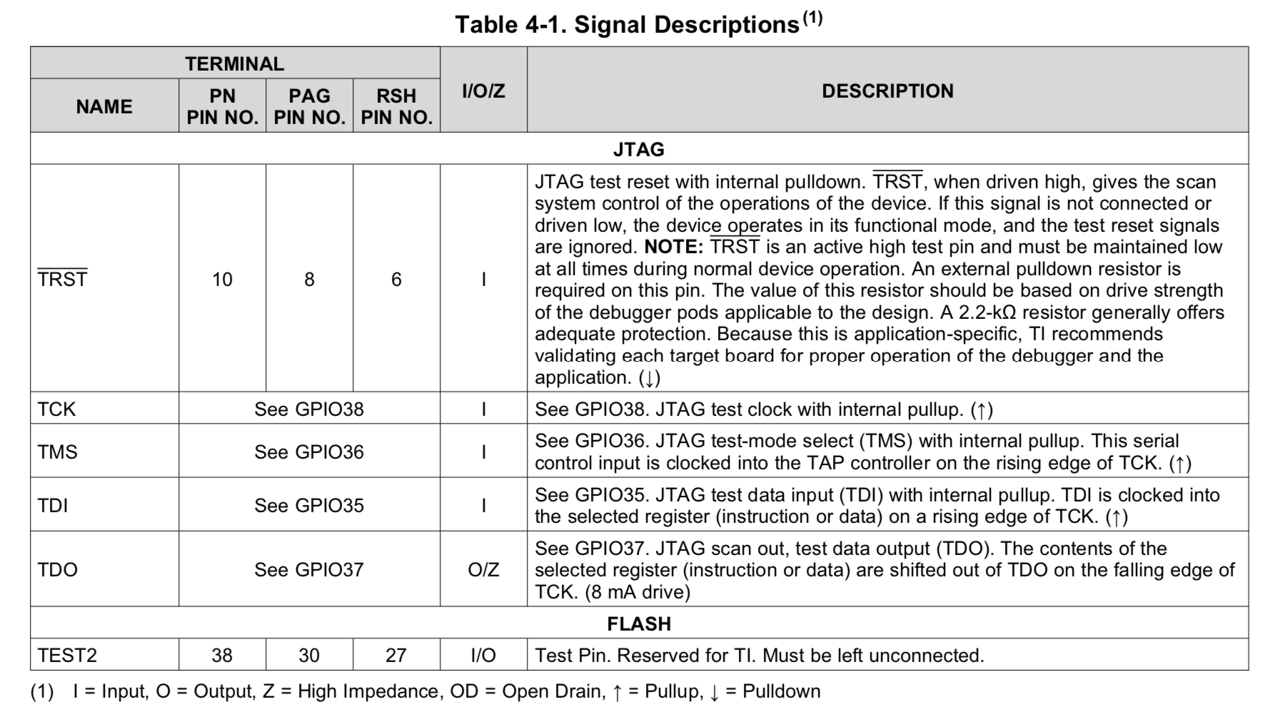
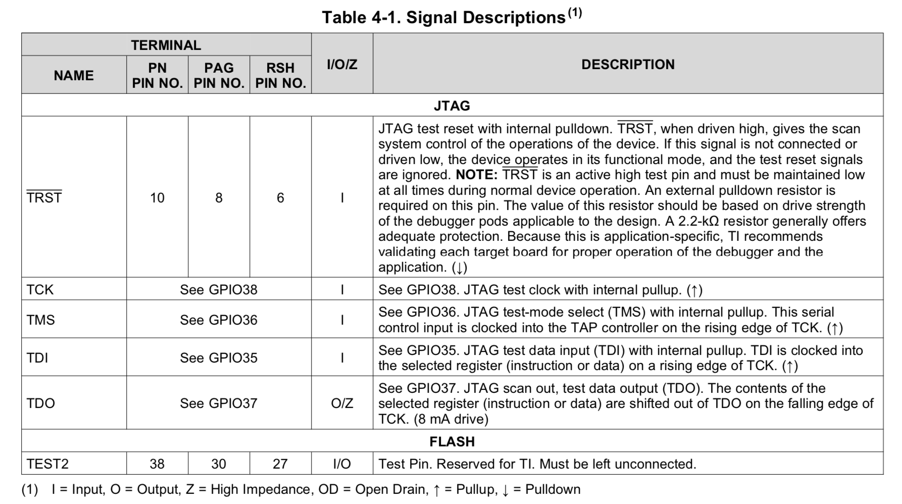
    2. What is the minimum pin to bring the uC to debug or program mode ( to download hex program into device), I suppose only these pin (TRST, TCK,TMS,TDI, TDO and GPIO 34. the TRST must be pulled low with 2.2k Ohm resistor

    3. Since I am using internal crystal i just pulled low pin X1 to ground, as mentioned below 

    4. The pin XRS should be pulled up by resistor to prevent uC reset, usually a push button reset connected to this pin, to bring XRS pin low, if we want to reset the device manually

    If you right click on your target.ccxml file there should be an option to "launch target config"  Please click on this, and we should observe the debug session launch correctly.

    If that works, then right click on the C28x_CPU0 target and select "connect target".  Please note if this is successful.  I beleive the target will auto-halt once this occurs, but if not you can halt the device manually.

    Assuming this works, you can the load your program manually, under the "debug" menu item you can load, load by project and select the .out file.

    I didn't see yet the correct menu in CCS as you mentioned, maybe this page, could you give more illustration with some picture


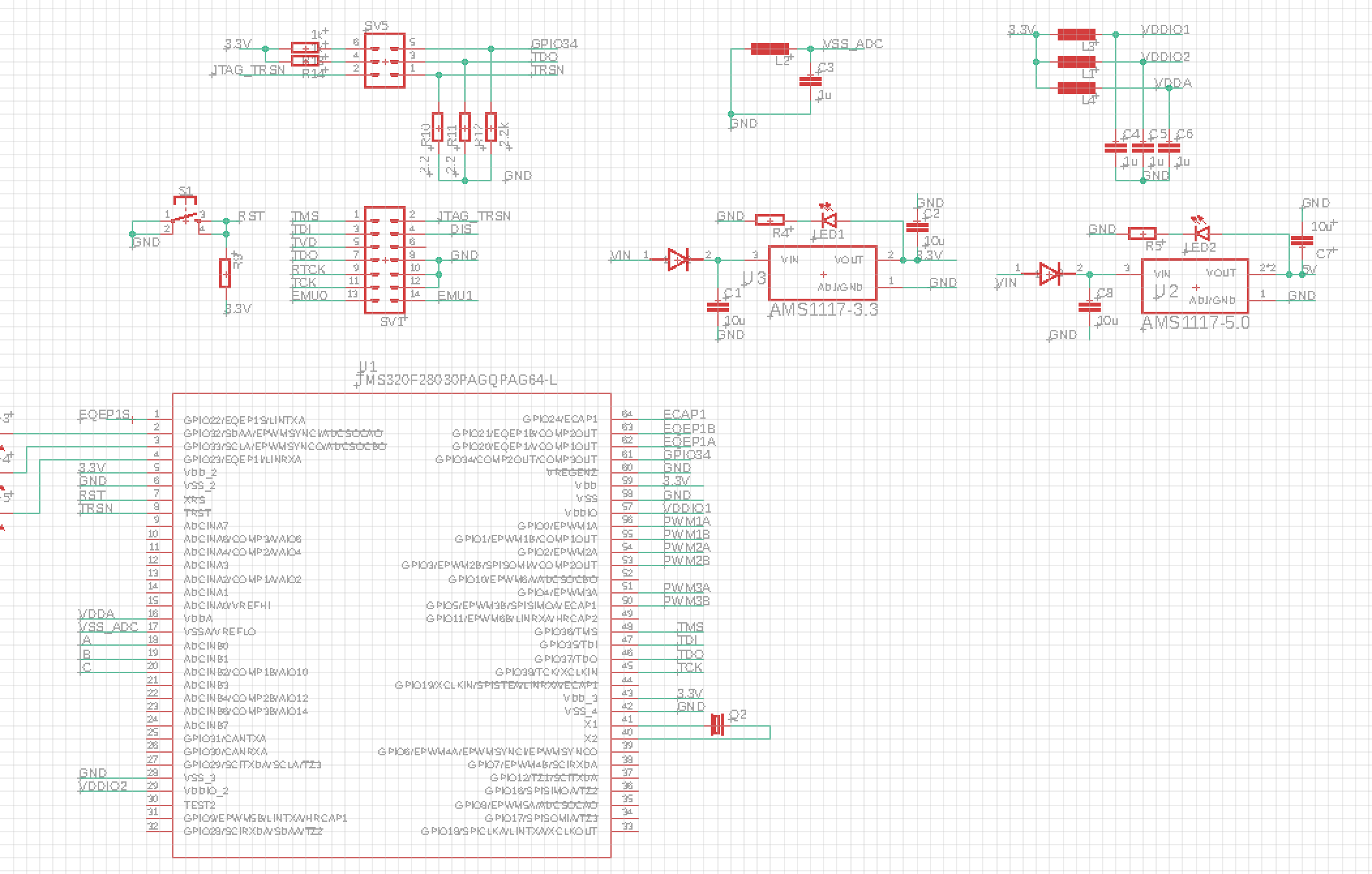
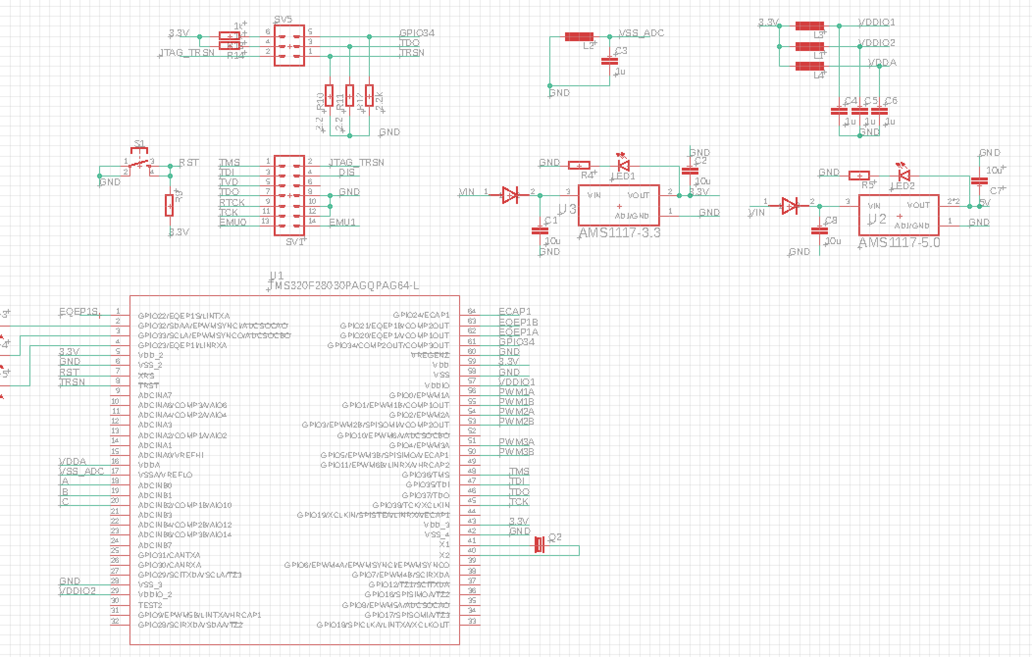
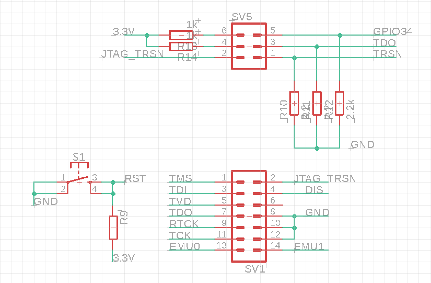
    Here my hardware connection that i use, maybe some connection was wrong, would you like check


    i look forward feedback from you

    Thank you

    BR

    Abdin

  • Abdin,

    Boot Mode 2 is correct, wait boot mode will prevent the device from trying to execute and of the programmed code that could potentially interfere with CCS establishing the connection across JTAG.  Once you are done with any debug, you'll want to change this back to the appropriate mode like boot from flash, etc.

    Your schematic looks good, proper pull downs on the correct pins, etc.

    I've uploaded a screenshot to show what I'd like you do to to connect.  If you right click on the target you should see this new submenu pop up; then you'll want to pick "Launch Selected Configuration" below.  Once you do this it should pull up the debugger view and you can then right click on the C28x CPU and then "connect target"