This thread has been locked.

If you have a related question, please click the "Ask a related question" button in the top right corner. The newly created question will be automatically linked to this question.

TIDM-1000: Questions for vienna demo board control

Part Number: TIDM-1000

Hi Guys,

We bought the Vienna demo board and F28379D control card from Ti. Now i want to start up the demo board. i have some questions about the board.

1.  what's the input voltage regulator capacity i need to connect? 

2. in the document, you said we needn't connect the neutrol from the input power grid, but when we start up the demo board step by step, we should connect the neatrol.

 so, we need to connect the neutrol, is it right? if yes, should i need a jumper from power neatrol to BUS neutrol?

3. whether the vienna board can work well, when the Three phase voltage is imbalance?

4. a, From the CCS project, i found the voltages are not tranfer to the actual value, but the control system can work normally. Can you tell me the  key point?

    b, i can't found where to use the measurements of the resistor voltages, is it reserved for control system?

Best regards,

Pan

  • Hi Pan pan,

    1.  what's the input voltage regulator capacity i need to connect? 

    Please refer to the tested power level in the user guide.

    2. in the document, you said we needn't connect the neutrol from the input power grid, but when we start up the demo board step by step, we should connect the neatrol.

    It actually depends on which build you are running. For build 1,2,3 you are suggested to connect the neutral. For build 4, you don't need to connect it.

     so, we need to connect the neutrol, is it right? if yes, should i need a jumper from power neatrol to BUS neutrol?

    You just need to connect the power supply neutral to the Bus mid point.

    3. whether the vienna board can work well, when the Three phase voltage is imbalance?

    If the imbalance is minor, it is fine. If not, it might be a problem.

    4. a, From the CCS project, i found the voltages are not tranfer to the actual value, but the control system can work normally. Can you tell me the  key point?

    The control system is based on per unit value while GUI value(actual value) is just for reference. 

        b, i can't found where to use the measurements of the resistor voltages, is it reserved for control system?

    If you are looking for the parameter of sensed voltage in the code, you could check ADC related code 


    Regards,

    Chen

  • Hi Chen,

    Glad to hear from you!

    1.  what's the input voltage regulator capacity i need to connect? 

    Please refer to the tested power level in the user guide.

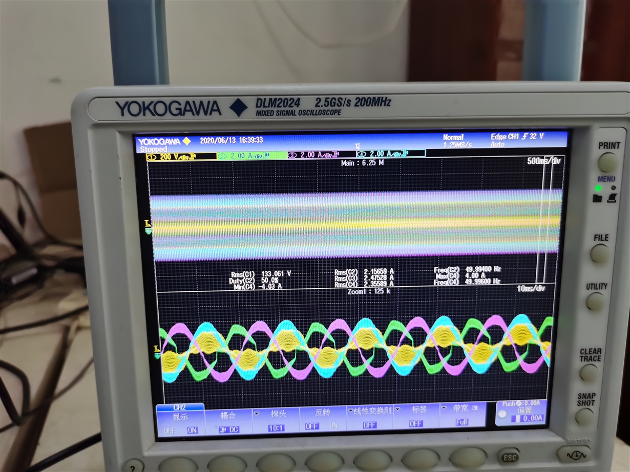
    I'm follow the reference design(TIDUCJOA) try to run the voltage 208V(L-L) power system with a voltage regulator 20KVA, but when the current feedback to the controller, the input voltage become distortion(CH1, YELLOW). So what should i do to solve it?


    2. in the document, you said we needn't connect the neutrol from the input power grid, but when we start up the demo board step by step, we should connect the neatrol.

    It actually depends on which build you are running. For build 1,2,3 you are suggested to connect the neutral. For build 4, you don't need to connect it.

     so, we need to connect the neutrol, is it right? if yes, should i need a jumper from power neatrol to BUS neutrol?

    You just need to connect the power supply neutral to the Bus mid point. ok

    3. whether the vienna board can work well, when the Three phase voltage is imbalance?

    If the imbalance is minor, it is fine. If not, it might be a problem.

    So about the minor, do you have any information?

    if i connect the power supply neutrol to DC bus mid point, even if the input voltage is imbalance, the board can work normally, is it right?

    4. a, From the CCS project, i found the voltages are not tranfer to the actual value, but the control system can work normally. Can you tell me the  key point?

    The control system is based on per unit value while GUI value(actual value) is just for reference. 

    I can found the below information:

    1.v1Meas = (((float32)(V1_ADC_READ1+V1_ADC_READ2+V1_ADC_READ3+V1_ADC_READ4))*ADC_PU_SCALE_FACTOR*0.25 - v1MeasOffset )*2.0;

    the founction of this formula is change the input voltage to -3.2~3.2. is it right?

    2. guiV1 = v1Meas * V_MAX_SENSE; #define V_MAX_SENSE (454);

    GUI value is meas multiplied by V_MAX_SENSE.

    the hareware circuit attenuation proportion is 2/3002(before amplifier)*8 (amplification)*0.8(adjust input voltage). the result is 234.53times. 

    these two amplifier times is not the same, is there any other details i missed?

        b, i can't found where to use the measurements of the resistor voltages, is it reserved for control system?

    If you are looking for the parameter of sensed voltage in the code, you could check ADC related code  ok

    After test the driver  signals, i found the drivers are the same for one phase. That's to say. the Signal Modulation is not the same as the Related Document from Hartmann. can you tell me the different?

    Regards,


    Pan


  • Hi,

    To answer some of your questions first.

    So about the minor, do you have any information?

    If it three phase current imbalance is minor, then it is acceptable. 

    if i connect the power supply neutrol to DC bus mid point, even if the input voltage is imbalance, the board can work normally, is it right?

    The ac input voltage should be balanced in general, otherwise we need to look into it. Could you post the expression window pic with all those ADC values?

    After test the driver  signals, i found the drivers are the same for one phase. That's to say. the Signal Modulation is not the same as the Related Document from Hartmann. can you tell me the different?

    Yes, the modulation is a little bit different. We have mentioned in the fig 4 in the user guide on the right side.

    Regards,

    Chen


  • Hi Chen,

    Thank you for your relpy!

    So about the minor, do you have any information?

    If it three phase current imbalance is minor, then it is acceptable. 

    I am a little confused that the imblance is point to current, not the voltage? For my understand, even if the voltage is imblance, the current should be equal.

     I want to know if the unblance factor can be quanitifed, 5% or else?

    if i connect the power supply neutrol to DC bus mid point, even if the input voltage is imbalance, the board can work normally, is it right?

    The ac input voltage should be balanced in general, otherwise we need to look into it. Could you post the expression window pic with all those ADC values?

    The uploaded picture, i want to show you, the input voltage(in yellow) was distorted by the control loop even if the input voltage regulator is 20kva. I want to know how to solve it.

    After test the driver  signals, i found the drivers are the same for one phase. That's to say. the Signal Modulation is not the same as the Related Document from Hartmann. can you tell me the different?

    Yes, the modulation is a little bit different. We have mentioned in the fig 4 in the user guide on the right side.

    In actually, i had my models for emulated by Simulink, these two different signal modulations have two results, the reference paper from Hartmann had better wave. So i want to  know  the reason you change the PWM signals.


    Pan

  • Hi Pan,

    Did you figure out this issue? 

    1. we don't have a quantified value for the imbalance. 

    2. Ok, so it appears under closed loop. Did you see this with open loop(build 1)?

    3. We have not compared with these two modulations. The reason we use that is because it is easy to implement and we didn't expect there are much difference between these two methods. But thanks for letting us know.

    Regards,

    Chen