This thread has been locked.

If you have a related question, please click the "Ask a related question" button in the top right corner. The newly created question will be automatically linked to this question.

TMS320F280049: Use HRPWM in complementary with exactly 50% duty

Part Number: TMS320F280049
Other Parts Discussed in Thread: C2000WARE

Dear champs,

I am asking this for our customer.

The user uses TI example "hrpwm_ex2_prdupdown_sfo_v8" with only modifying following line 286 and line 287 to set PWM1A and PWM1B in complementary.

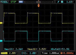
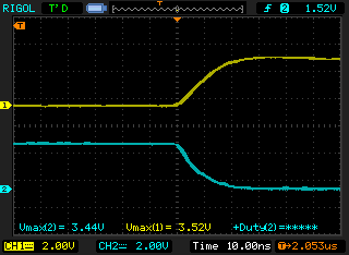
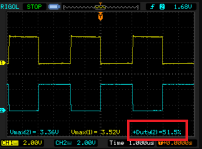
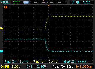
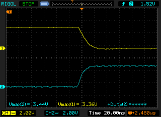
On the oscilloscope snapshot below, the duty time of PWM 1A differs from the duty time of PWM 1B by about 17.6 ns. It appears the duty of yellow is larger than that of blue, which is not desired.

Questions:

1. In theory, the duty should be 50% in PWM1A and PWM1B. Why the difference time of PWM1A duty and PWM 1B duty is so large up to 10 to 20 ns, especially they are in HRPWM? The user desires the difference should be around 150 ps.

2. The user's goal is to have PWM 1A and 1B in complementary with 50% duty with fixed or changing periods. And the duty difference of PWM1A and PWM1B should be around 150 ps. What should the user do? 

Wayne Huang

  • Wayne,

    I'd have to check something first, I have never seen CBU clearing the EPWM and CBD setting the EPWM in HRMODE. I'll get back to you.

    Nima

  • Dear Nima,

    Do you have any update?

    Did you see this issue on your side, too?

    Is this a limitation or is there anything wrong with our example code or their usage?

    Wayne Huang

  • Do you have your epwm setting so I can check it out? 

  • Dear Nima,

    As I mentioned in the first post, they use our example with only modifying two lines.

    So, the other PWM setting is just same as our example codes.

    Wayne Huang

  • I am not able to see this on my setup. Here is the example code I wrote to check with this. The edges seem to line up perfectly.

    //#############################################################################
    //
    // FILE:   hrpwm_ex4_duty_updown_sfo.c
    //
    // TITLE:  HRPWM Duty Control with UPDOWN Mode.
    //
    //! \addtogroup driver_example_list
    //! <h1>HRPWM Duty Control with UPDOWN Mode</h1>
    //!
    //
    //
    //#############################################################################
    // $TI Release: $
    // $Release Date: $
    // $Copyright: $
    //#############################################################################
    
    
    //
    // Included Files
    //
    #include "driverlib.h"
    #include "device.h"
    #include "SFO_V8.h"
    
    #define CHANNEL_B_AS_ZRO_PRD_REF    0
    #define EPWM_TIMER_TBPRD            100UL
    #define MIN_HRPWM_DUTY_PERCENT      4.0/((float32_t)EPWM_TIMER_TBPRD)*100.0
    //
    // Defines
    //
    #define LAST_EPWM_INDEX_FOR_EXAMPLE    5
    
    //
    // Globals
    //
    
    float32_t dutyFine = 50.0;
    uint16_t status;
    
    int MEP_ScaleFactor; // Global variable used by the SFO library
                         // Result can be used for all HRPWM channels
                         // This variable is also copied to HRMSTEP
                         // register by SFO() function.
    
    volatile uint32_t ePWM[] =
        {0, EPWM1_BASE, EPWM2_BASE, EPWM3_BASE, EPWM4_BASE};
    //
    // Function Prototypes
    //
    void initHRPWM(uint32_t period);
    void initEPWMGpio(void);
    void error(void);
    //__interrupt void epwm1ISR(void);
    //__interrupt void epwm2ISR(void);
    //__interrupt void epwm3ISR(void);
    //__interrupt void epwm4ISR(void);
    
    //
    // Main
    //
    void main(void)
    {
        uint16_t i = 0;
    
        //
        // Initialize device clock and peripherals
        //
        Device_init();
    
        //
        // Disable pin locks and enable internal pull ups.
        //
        Device_initGPIO();
    
        //
        // Initialize PIE and clear PIE registers. Disables CPU interrupts.
        //
        Interrupt_initModule();
    
        //
        // Initialize the PIE vector table with pointers to the shell Interrupt
        // Service Routines (ISR).
        //
        Interrupt_initVectorTable();
    
        //
        // Assign the interrupt service routines to ePWM interrupts
        //
        //Interrupt_register(INT_EPWM1, &epwm1ISR);
        //Interrupt_register(INT_EPWM2, &epwm2ISR);
        //Interrupt_register(INT_EPWM3, &epwm3ISR);
        //Interrupt_register(INT_EPWM4, &epwm4ISR);
    
        initEPWMGpio();
    
    
        //
        // CHANGE XBAR inputs from using GPIO0
        // if EPWM SYNCIN is enabled, EXTSYNCIN1 and EXTSYNCIN2 will use
        // GPIO0 (which is the output of EPWM1).
        // Pick and unused GPIO
        //
        XBAR_setInputPin(XBAR_INPUT5, 50);
        XBAR_setInputPin(XBAR_INPUT6, 50);
    
    
        //
        // Calling SFO() updates the HRMSTEP register with calibrated MEP_ScaleFactor.
        // HRMSTEP must be populated with a scale factor value prior to enabling
        // high resolution period control.
        //
        while(status == SFO_INCOMPLETE)
        {
            status = SFO();
            if(status == SFO_ERROR)
            {
                error();   // SFO function returns 2 if an error occurs & # of MEP
            }              // steps/coarse step exceeds maximum of 255.
        }


        //
        // Disable sync(Freeze clock to PWM as well)
        //
        SysCtl_disablePeripheral(SYSCTL_PERIPH_CLK_GTBCLKSYNC);
        SysCtl_disablePeripheral(SYSCTL_PERIPH_CLK_TBCLKSYNC);
    
        initHRPWM(EPWM_TIMER_TBPRD);
    
        //
        // Enable sync and clock to PWM
        //
        SysCtl_enablePeripheral(SYSCTL_PERIPH_CLK_TBCLKSYNC);
    
    
        // Enable ePWM interrupts
        //
        //Interrupt_enable(INT_EPWM1);
        //Interrupt_enable(INT_EPWM2);
        //Interrupt_enable(INT_EPWM3);
        //Interrupt_enable(INT_EPWM4);
    
        //
        // Enable Global Interrupt (INTM) and realtime interrupt (DBGM)
        //
        EINT;
        ERTM;
    
    
        for(;;)
        {
             //
             // Sweep DutyFine
             //
             for(dutyFine = MIN_HRPWM_DUTY_PERCENT; dutyFine < (100.0-MIN_HRPWM_DUTY_PERCENT); dutyFine += 0.01)
             {
                 DEVICE_DELAY_US(1000);
                 for(i=1; i<LAST_EPWM_INDEX_FOR_EXAMPLE; i++)
                 {
                     float32_t count = ((100.0 - dutyFine) * (float32_t)(EPWM_TIMER_TBPRD << 8))/100.0;
                     uint32_t compCount = (count);
                     uint32_t hrCompCount = (compCount & (0x000000FF));
                     if (hrCompCount == 0)
                     {
                         //
                         // Add 1 to not have CMPxHR = 0
                         //
                         compCount |= 0x00000001;
                     }
                     HRPWM_setCounterCompareValue(ePWM[i], HRPWM_COUNTER_COMPARE_A, compCount);
    #if CHANNEL_B_AS_ZRO_PRD_REF == 0
                     HRPWM_setCounterCompareValue(ePWM[i], HRPWM_COUNTER_COMPARE_B, compCount);
    #endif
                 }
    
                 //
                 // Call the scale factor optimizer lib function SFO()
                 // periodically to track for any change due to temp/voltage.
                 // This function generates MEP_ScaleFactor by running the
                 // MEP calibration module in the HRPWM logic. This scale
                 // factor can be used for all HRPWM channels. The SFO()
                 // function also updates the HRMSTEP register with the
                 // scale factor value.
                 //
                 status = SFO(); // in background, MEP calibration module
                                 // continuously updates MEP_ScaleFactor
    
                 if (status == SFO_ERROR)
                 {
                     error();   // SFO function returns 2 if an error occurs & #
                                // of MEP steps/coarse step
                 }              // exceeds maximum of 255.
             }
         }
    }
    
    //
    // epwm1ISR - ePWM 1 ISR
    //
    //__interrupt void epwm1ISR(void)
    //{
    //    EPWM_clearEventTriggerInterruptFlag(EPWM1_BASE);
    //    Interrupt_clearACKGroup(INTERRUPT_ACK_GROUP3);
    //}
    
    //
    // epwm2ISR - ePWM 2 ISR
    //
    //__interrupt void epwm2ISR(void)
    //{
    //    EPWM_clearEventTriggerInterruptFlag(EPWM2_BASE);
    //    Interrupt_clearACKGroup(INTERRUPT_ACK_GROUP3);
    //}
    
    //
    // epwm3ISR - ePWM 3 ISR
    //
    //__interrupt void epwm3ISR(void)
    //{
    //    EPWM_clearEventTriggerInterruptFlag(EPWM3_BASE);
    //    Interrupt_clearACKGroup(INTERRUPT_ACK_GROUP3);
    //}
    
    //
    // epwm4ISR - ePWM 4 ISR
    //
    //__interrupt void epwm4ISR(void)
    //{
    //    EPWM_clearEventTriggerInterruptFlag(EPWM4_BASE);
    //    Interrupt_clearACKGroup(INTERRUPT_ACK_GROUP3);
    //}


    void initEPWMGpio(void)
    {
        //
        // Configure GPIO0/1 as ePWM1A/1B pins respectively
        //
        GPIO_setPadConfig(0, GPIO_PIN_TYPE_STD);
        GPIO_setPinConfig(GPIO_0_EPWM1A);
        GPIO_setPadConfig(1, GPIO_PIN_TYPE_STD);
        GPIO_setPinConfig(GPIO_1_EPWM1B);
    
        //
        // Configure GPIO2/3 as ePWM2A/2B pins respectively
        //
        GPIO_setPadConfig(2, GPIO_PIN_TYPE_STD);
        GPIO_setPinConfig(GPIO_2_EPWM2A);
        GPIO_setPadConfig(3, GPIO_PIN_TYPE_STD);
        GPIO_setPinConfig(GPIO_3_EPWM2B);
    
        //
        // Configure GPIO4/5 as ePWM3A/3B pins respectively
        //
        GPIO_setPadConfig(4, GPIO_PIN_TYPE_STD);
        GPIO_setPinConfig(GPIO_4_EPWM3A);
        GPIO_setPadConfig(5, GPIO_PIN_TYPE_STD);
        GPIO_setPinConfig(GPIO_5_EPWM3B);
    
        //
        // Configure GPIO6/7 as ePWM4A/4B pins respectively
        //
        GPIO_setPadConfig(6, GPIO_PIN_TYPE_STD);
        GPIO_setPinConfig(GPIO_6_EPWM4A);
        GPIO_setPadConfig(7, GPIO_PIN_TYPE_STD);
        GPIO_setPinConfig(GPIO_7_EPWM4B);
    }
    
    void initHRPWM(uint32_t period)
    {
    
        uint16_t j;
    
        //
        // ePWM channel register configuration with HRPWM
        // ePWMxA / ePWMxB toggle low/high with MEP control on Rising and Falling edges
        //
        for (j=1;j<LAST_EPWM_INDEX_FOR_EXAMPLE;j++)
        {
            EPWM_setEmulationMode(ePWM[j], EPWM_EMULATION_FREE_RUN);
    
            //
            // Set-up TBCLK
            //
            EPWM_setTimeBasePeriod(ePWM[j], period-1);
            EPWM_setPhaseShift(ePWM[j], 0U);
            EPWM_setTimeBaseCounter(ePWM[j], 0U);
    
            //
            // set duty 50% initially
            //
            HRPWM_setCounterCompareValue(ePWM[j], HRPWM_COUNTER_COMPARE_A, (period/2 << 8) + 1);
            HRPWM_setCounterCompareValue(ePWM[j], HRPWM_COUNTER_COMPARE_B, (period/2 << 8) + 1);
    
    
            //
            // Set up counter mode
            //
            EPWM_setTimeBaseCounterMode(ePWM[j], EPWM_COUNTER_MODE_UP_DOWN);
            EPWM_disablePhaseShiftLoad(ePWM[j]);
            EPWM_setClockPrescaler(ePWM[j],
                                   EPWM_CLOCK_DIVIDER_1,
                                   EPWM_HSCLOCK_DIVIDER_1);
            EPWM_setSyncOutPulseMode(ePWM[j], EPWM_SYNC_OUT_PULSE_DISABLED);
    
    
            //
            // Set up shadowing
            // MUST BE CTR=(ZER & PRD)
            //
            EPWM_setCounterCompareShadowLoadMode(ePWM[j],
                                                 EPWM_COUNTER_COMPARE_A,
                                                 EPWM_COMP_LOAD_ON_CNTR_ZERO_PERIOD);
            EPWM_setCounterCompareShadowLoadMode(ePWM[j],
                                                 EPWM_COUNTER_COMPARE_B,
                                                 EPWM_COMP_LOAD_ON_CNTR_ZERO_PERIOD);
    
            //
            // Set actions
            //
    
            EPWM_setActionQualifierAction(ePWM[j],
                                          EPWM_AQ_OUTPUT_A,
                                          EPWM_AQ_OUTPUT_HIGH,
                                          EPWM_AQ_OUTPUT_ON_TIMEBASE_UP_CMPA);
            EPWM_setActionQualifierAction(ePWM[j],
                                          EPWM_AQ_OUTPUT_A,
                                          EPWM_AQ_OUTPUT_LOW,
                                          EPWM_AQ_OUTPUT_ON_TIMEBASE_DOWN_CMPA);
    
    #if CHANNEL_B_AS_ZRO_PRD_REF == 1
            //
            // Use B channel as the ZERO and PRD reference
            //
            EPWM_setActionQualifierAction(ePWM[j],
                                          EPWM_AQ_OUTPUT_B,
                                          EPWM_AQ_OUTPUT_HIGH,
                                          EPWM_AQ_OUTPUT_ON_TIMEBASE_ZERO);
            EPWM_setActionQualifierAction(ePWM[j],
                                          EPWM_AQ_OUTPUT_B,
                                          EPWM_AQ_OUTPUT_LOW,
                                          EPWM_AQ_OUTPUT_ON_TIMEBASE_PERIOD);
    #else
            EPWM_setActionQualifierAction(ePWM[j],
                                          EPWM_AQ_OUTPUT_B,
                                          EPWM_AQ_OUTPUT_LOW,
                                          EPWM_AQ_OUTPUT_ON_TIMEBASE_UP_CMPB);
            EPWM_setActionQualifierAction(ePWM[j],
                                          EPWM_AQ_OUTPUT_B,
                                          EPWM_AQ_OUTPUT_HIGH,
                                          EPWM_AQ_OUTPUT_ON_TIMEBASE_DOWN_CMPB);
    #endif
    
    
            HRPWM_setMEPEdgeSelect(ePWM[j], HRPWM_CHANNEL_A, HRPWM_MEP_CTRL_RISING_AND_FALLING_EDGE);
            HRPWM_setMEPControlMode(ePWM[j], HRPWM_CHANNEL_A, HRPWM_MEP_DUTY_PERIOD_CTRL);
    
            //
            // Set up shadowing
            // MUST BE CTR=(ZER & PRD)
            //
            HRPWM_setCounterCompareShadowLoadEvent(ePWM[j], HRPWM_CHANNEL_A, HRPWM_LOAD_ON_CNTR_ZERO_PERIOD);
    
    #if CHANNEL_B_AS_ZRO_PRD_REF == 0
            HRPWM_setMEPEdgeSelect(ePWM[j], HRPWM_CHANNEL_B, HRPWM_MEP_CTRL_RISING_AND_FALLING_EDGE);
            HRPWM_setMEPControlMode(ePWM[j], HRPWM_CHANNEL_B, HRPWM_MEP_DUTY_PERIOD_CTRL);
    
            //
            // Set up shadowing
            // MUST BE CTR=(ZER & PRD)
            //
            HRPWM_setCounterCompareShadowLoadEvent(ePWM[j], HRPWM_CHANNEL_B, HRPWM_LOAD_ON_CNTR_ZERO_PERIOD);
    #endif
    
            HRPWM_enableAutoConversion(ePWM[j]);
    
            //
            // Turn on high-resolution period control for DUTY to take HR on BOTH EDGEs.
            //
    
            HRPWM_enablePeriodControl(ePWM[j]);
            HRPWM_disablePhaseShiftLoad(ePWM[j]);
    
    
            //
            // Interrupt where we will change the Compare Values
            // Select INT on Time base counter zero event,
            // Enable INT, generate INT on 1st event
            //
            //EPWM_setInterruptSource(ePWM[j], EPWM_INT_TBCTR_ZERO);
            //EPWM_enableInterrupt(ePWM[j]);
            //EPWM_setInterruptEventCount(ePWM[j], 1U);
        }
    
    }
    
    //
    // error - Halt debugger when called
    //
    void error (void)
    {
        ESTOP0;         // Stop here and handle error
    }


    The results tested at many different duty cylces. This one is at 52.5%, all other were the same:

  • Dear Nima,

    We are still confused.

    Would you please make it clearer?

    1) The user cares about the "resolution of duty", not the alignment of rising edge and falling edge.

    They think the duty resolution should be about ~150ps. In your above figure, you said you set 52.5%, but the figure showed it was 51.5%. Why was there 1% duty difference? Was there anything wrong? 

    2) In our previous posts, we said the user used TI example code (C:\TI\c2000\C2000Ware_3_02_00_00\device_support\f28002x\examples\hrpwm\hrpwm_ex2_prdupdown_sfo_v8.c) with modifying only two lines showed on TI F280049 control card in the first post. Did you reproduce the same on your side? Because you used different example codes in the last post, we are not sure if you saw the same issue but you resolved it by your own code? If so, would you please show us explicitly what the problem was? Is there anything wrong with hrpwm_ex2_prdupdown_sfo_v8.c or was the user's usage (two line modifying) wrong? We need to clarify the root cause. That is, we are not sure if this example code "hrpwm_ex2_prdupdown_sfo_v8.c" has something wrong.

    Wayne Huang

  • 1. Yes you will have 150ps resolution. The steps will be correct on both A and B channel. Try the code I sent you.

    51.5% sorry for the incorrect number.

    2. I will try that example and send you the results. I worked from the example I wrote to make sure no incorrect setting are there for the code I sent you.

  • Used the same code, changed the action qualifier as mentioned. Two lines only. everything works perfectly.

    Customer is incorrect. 150ps resolution with edges in the correct location with the settnig you requested.

  • Dear Nima,

    Per our offline discussion, the user should also control duty and update CMPAHR and CMPBHR along with updating TBPRDHR for keeping 50% duty in high resolution.

    (*ePWM[i]).CMPA.bit.CMPAHR = PeriodFine/2;

    (*ePWM[i]).CMPB.bit.CMPBHR = PeriodFine/2; 

    I attached the code that has been verified.

    Thank you very much for you support.

    Wayne Huang

    //#############################################################################
    //
    // FILE:    hrpwm_ex2_prdupdown_sfo_v8.c
    //
    // TITLE:   HRPWM SFO V8 High-Resolution Period (Up-Down Count) example
    //
    //! \addtogroup bitfield_example_list
    //! <h1>HRPWM Period Up-Down Count</h1>
    //!
    //! This example modifies the MEP control registers to show edge displacement
    //! for high-resolution period with ePWM in Up-Down count mode
    //! due to the HRPWM control extension of the respective ePWM module.
    //!
    //! This example calls the following TI's MEP Scale Factor Optimizer (SFO)
    //! software library V8 functions:
    //!
    //! \b int \b SFO(); \n
    //! updates MEP_ScaleFactor dynamically when HRPWM is in use
    //! updates HRMSTEP register (exists only in EPwm1Regs register space)
    //! with MEP_ScaleFactor value
    //! - returns 2 if error: MEP_ScaleFactor is greater than maximum value of 255
    //!   (Auto-conversion may not function properly under this condition)
    //! - returns 1 when complete for the specified channel
    //! - returns 0 if not complete for the specified channel
    //!
    //! This example is intended to explain the HRPWM capabilities. The code can be
    //! optimized for code efficiency. Refer to TI's Digital power application
    //! examples and TI Digital Power Supply software libraries for details.
    //!
    //! To run this example:
    //! -# Run this example at maximum SYSCLKOUT
    //! -# Activate Real time mode
    //! -# Run the code
    //!
    //! \b External \b Connections \n
    //!  - Monitor ePWM1 A/B pins on an oscilloscope.
    //!
    //! \b Watch \b Variables \n
    //!  - UpdateFine - Set to 1 use HRPWM capabilities and observe in fine MEP
    //!                 steps(default)
    //!                 Set to 0 to disable HRPWM capabilities and observe in
    //!                 coarse SYSCLKOUT cycle steps
    //!
    //
    //#############################################################################
    // $TI Release: F28004x Support Library v1.10.00.00 $
    // $Release Date: Tue May 26 17:06:03 IST 2020 $
    // $Copyright:
    // Copyright (C) 2020 Texas Instruments Incorporated - http://www.ti.com/
    //
    // Redistribution and use in source and binary forms, with or without 
    // modification, are permitted provided that the following conditions 
    // are met:
    // 
    //   Redistributions of source code must retain the above copyright 
    //   notice, this list of conditions and the following disclaimer.
    // 
    //   Redistributions in binary form must reproduce the above copyright
    //   notice, this list of conditions and the following disclaimer in the 
    //   documentation and/or other materials provided with the   
    //   distribution.
    // 
    //   Neither the name of Texas Instruments Incorporated nor the names of
    //   its contributors may be used to endorse or promote products derived
    //   from this software without specific prior written permission.
    // 
    // THIS SOFTWARE IS PROVIDED BY THE COPYRIGHT HOLDERS AND CONTRIBUTORS 
    // "AS IS" AND ANY EXPRESS OR IMPLIED WARRANTIES, INCLUDING, BUT NOT 
    // LIMITED TO, THE IMPLIED WARRANTIES OF MERCHANTABILITY AND FITNESS FOR
    // A PARTICULAR PURPOSE ARE DISCLAIMED. IN NO EVENT SHALL THE COPYRIGHT 
    // OWNER OR CONTRIBUTORS BE LIABLE FOR ANY DIRECT, INDIRECT, INCIDENTAL, 
    // SPECIAL, EXEMPLARY, OR CONSEQUENTIAL DAMAGES (INCLUDING, BUT NOT 
    // LIMITED TO, PROCUREMENT OF SUBSTITUTE GOODS OR SERVICES; LOSS OF USE,
    // DATA, OR PROFITS; OR BUSINESS INTERRUPTION) HOWEVER CAUSED AND ON ANY
    // THEORY OF LIABILITY, WHETHER IN CONTRACT, STRICT LIABILITY, OR TORT 
    // (INCLUDING NEGLIGENCE OR OTHERWISE) ARISING IN ANY WAY OUT OF THE USE 
    // OF THIS SOFTWARE, EVEN IF ADVISED OF THE POSSIBILITY OF SUCH DAMAGE.
    // $
    //#############################################################################
    
    //
    // Included Files
    //
    #include "F28x_Project.h"
    #include "SFO_V8.h"
    
    //
    // Defines
    //
    #define PWM_CH            2        // # of PWM channels - 1
    #define STATUS_SUCCESS    1
    #define STATUS_FAIL       0
    
    //
    // Globals
    //
    uint16_t UpdateFine, PeriodFine, status;
    int MEP_ScaleFactor; // Global variable used by the SFO library
                         // Result can be used for all HRPWM channels
                         // This variable is also copied to HRMSTEP
                         // register by SFO(0) function.
    
    // Used by SFO library (ePWM[0] is a dummy value that isn't used)
    volatile struct EPWM_REGS *ePWM[PWM_CH] = {&EPwm1Regs, &EPwm1Regs};
    
    //
    // Function Prototypes
    //
    void initHRPWM1GPIO(void);
    void configHRPWM(uint16_t period);
    void error(void);
    
    //
    // Main
    //
    void main(void)
    {
        uint16_t i;
    
        //
        // Initialize device clock and peripherals
        //
        InitSysCtrl();
    
        //
        // Initialize GPIO
        //
        InitGpio();
        initHRPWM1GPIO();
    
        //
        // Initialize PIE and clear PIE registers. Disables CPU interrupts.
        //
        DINT;
        InitPieCtrl();
        IER = 0x0000;
        IFR = 0x0000;
    
        //
        // Initialize the PIE vector table with pointers to the shell Interrupt
        // Service Routines (ISR).
        //
        InitPieVectTable();
    
        //
        // Setup example variables
        //
        UpdateFine = 1;
        PeriodFine = 0;
        status = SFO_INCOMPLETE;
    
        //
        // Enable Global Interrupt (INTM) and realtime interrupt (DBGM)
        //
        EINT;
        ERTM;
        
        //
        // ePWM and HRPWM register initialization
        //
        for(i=1; i<PWM_CH; i++)
        {
            // Change clock divider to /1
            // (PWM clock needs to be > 60MHz)
            (*ePWM[i]).TBCTL.bit.HSPCLKDIV = 0;
        }    
        configHRPWM(20);
        
        //
        // Calling SFO() updates the HRMSTEP register with calibrated MEP_ScaleFactor.
        // HRMSTEP must be populated with a scale factor value prior to enabling
        // high resolution period control.
        //
        while(status == SFO_INCOMPLETE)
        {
            status = SFO();
            if (status == SFO_ERROR)
            {
                error();    // SFO function returns 2 if an error occurs & # of MEP
            }               // steps/coarse step exceeds maximum of 255.
        }
    
        for(;;)
        {
            //
            // Sweep PeriodFine as a Q16 number from 0.2 - 0.999
            //
            for(PeriodFine = 0x3333; PeriodFine < 0xFFBF; PeriodFine++)
            {
                if(UpdateFine)
                {
                    //
                    // Because auto-conversion is enabled, the desired
                    // fractional period must be written directly to the
                    // TBPRDHR register in Q16 format
                    // (lower 8-bits are ignored)
                    //
                    // EPwm1Regs.TBPRDHR = PeriodFine;
                    //
                    // The hardware will automatically scale
                    // the fractional period by the MEP_ScaleFactor
                    // in the HRMSTEP register (which is updated
                    // by the SFO calibration software).
                    //
                    // Hardware conversion:
                    // MEP delay movement = ((TBPRDHR(15:0) >> 8) *  HRMSTEP(7:0) +
                    //                       0x80) >> 8
                    //
                    for(i=1; i<PWM_CH; i++)
                    {
                        (*ePWM[i]).TBPRDHR = PeriodFine; //In Q16 format
                        (*ePWM[i]).CMPA.bit.CMPAHR = PeriodFine/2;           // [20200810 Wayne] Update CMPAHR as well with TBPRDHR
                        (*ePWM[i]).CMPB.bit.CMPBHR = PeriodFine/2;           // [20200810 Wayne] Update CMPBHR as well with TBPRDHR
                    }
                }
                else
                {
                    //
                    // No high-resolution movement on TBPRDHR.
                    //
                    for(i=1; i<PWM_CH; i++)
                    {
                        (*ePWM[i]).TBPRDHR = 0;
                    }
                }
    
                //
                // Call the scale factor optimizer lib function SFO(0)
                // periodically to track for any change due to temp/voltage.
                // This function generates MEP_ScaleFactor by running the
                // MEP calibration module in the HRPWM logic. This scale
                // factor can be used for all HRPWM channels. HRMSTEP
                // register is automatically updated by the SFO function.
                //
                status = SFO(); // in background, MEP calibration module
                                // continuously updates MEP_ScaleFactor
    
                if(status == SFO_ERROR)
                {
                    error();   // SFO function returns 2 if an error occurs & # of
                               // MEP steps/coarse step exceeds maximum of 255.
                }
            } // end PeriodFine for loop
        } // end infinite for loop
    }
    
    //
    // configHRPWM - Configures all ePWM channels and sets up HRPWM
    //                on ePWMxA channels &  ePWMxB channels
    //
    void configHRPWM(uint16_t period)
    {
        uint16_t j;
    
        //
        // ePWM channel register configuration with HRPWM
        // ePWMxA toggle low/high with MEP control on Rising edge
        //
        EALLOW;
        CpuSysRegs.PCLKCR0.bit.TBCLKSYNC = 0;   // Disable TBCLK within the EPWM
        EDIS;
    
        for(j=1; j<PWM_CH; j++)
        {
            (*ePWM[j]).TBCTL.bit.PRDLD = TB_SHADOW;  // set Shadow load
            (*ePWM[j]).TBPRD = period;               // PWM frequency = 1/(2*TBPRD)
            (*ePWM[j]).CMPA.bit.CMPA = period / 2;   // set duty 50% initially
            (*ePWM[j]).CMPA.bit.CMPAHR = (1 << 8);   // initialize HRPWM extension
            (*ePWM[j]).CMPB.bit.CMPB = period / 2;   // set duty 50% initially
            (*ePWM[j]).CMPB.all |= 1;
            (*ePWM[j]).TBPHS.all = 0;
            (*ePWM[j]).TBCTR = 0;
    
            (*ePWM[j]).TBCTL.bit.CTRMODE = TB_COUNT_UPDOWN; // Select up-down
                                                            // count mode
            (*ePWM[j]).TBCTL.bit.SYNCOSEL = TB_SYNC_DISABLE;
            (*ePWM[j]).TBCTL.bit.HSPCLKDIV = TB_DIV1;
            (*ePWM[j]).TBCTL.bit.CLKDIV = TB_DIV1;          // TBCLK = SYSCLKOUT
            (*ePWM[j]).TBCTL.bit.FREE_SOFT = 11;
    
            (*ePWM[j]).CMPCTL.bit.LOADAMODE = CC_CTR_ZERO;  // LOAD CMPA on CTR = 0
            (*ePWM[j]).CMPCTL.bit.LOADBMODE = CC_CTR_ZERO;
            (*ePWM[j]).CMPCTL.bit.SHDWAMODE = CC_SHADOW;
            (*ePWM[j]).CMPCTL.bit.SHDWBMODE = CC_SHADOW;
    
            (*ePWM[j]).AQCTLA.bit.CAU = AQ_SET;             // PWM toggle high/low
            (*ePWM[j]).AQCTLA.bit.CAD = AQ_CLEAR;
            (*ePWM[j]).AQCTLB.bit.CBU = AQ_CLEAR;             // PWM toggle high/low
            (*ePWM[j]).AQCTLB.bit.CBD = AQ_SET;
    
    
            EALLOW;
            (*ePWM[j]).HRCNFG.all = 0x0;
            (*ePWM[j]).HRCNFG.bit.EDGMODE = HR_BEP;          // MEP control on
                                                             // both edges.
            (*ePWM[j]).HRCNFG.bit.CTLMODE = HR_CMP;          // CMPAHR and TBPRDHR
                                                             // HR control.
            (*ePWM[j]).HRCNFG.bit.HRLOAD = HR_CTR_ZERO_PRD;  // load on CTR = 0
                                                             // and CTR = TBPRD
            (*ePWM[j]).HRCNFG.bit.EDGMODEB = HR_BEP;         // MEP control on
                                                             // both edges
            (*ePWM[j]).HRCNFG.bit.CTLMODEB = HR_CMP;         // CMPBHR and TBPRDHR
                                                             // HR control
            (*ePWM[j]).HRCNFG.bit.HRLOADB = HR_CTR_ZERO_PRD; // load on CTR = 0
                                                             // and CTR = TBPRD
            (*ePWM[j]).HRCNFG.bit.AUTOCONV = 1;        // Enable autoconversion for
                                                       // HR period
    
            (*ePWM[j]).HRPCTL.bit.TBPHSHRLOADE = 1;    // Enable TBPHSHR sync
                                                       // (required for updwn
                                                       //  count HR control)
            (*ePWM[j]).HRPCTL.bit.HRPE = 1;            // Turn on high-resolution
                                                       // period control.
    
            CpuSysRegs.PCLKCR0.bit.TBCLKSYNC = 1;      // Enable TBCLK within
                                                       // the EPWM
            (*ePWM[j]).TBCTL.bit.SWFSYNC = 1;          // Synchronize high
                                                       // resolution phase to
                                                       // start HR period
            EDIS;
        }
    }
    
    //
    // initHRPWM1GPIO - Initialize HRPWM1 GPIOs
    //
    void initHRPWM1GPIO(void)
    {
        EALLOW;
    
        //
        // Disable internal pull-up for the selected output pins
        // for reduced power consumption
        // Pull-ups can be enabled or disabled by the user.
        //
        GpioCtrlRegs.GPAPUD.bit.GPIO0 = 1;    // Disable pull-up on GPIO0 (EPWM1A)
        GpioCtrlRegs.GPAPUD.bit.GPIO1 = 1;    // Disable pull-up on GPIO1 (EPWM1B)
    
        //
        // Configure EPWM-1 pins using GPIO regs
        // This specifies which of the possible GPIO pins will be EPWM1 functional
        // pins.
        //
        GpioCtrlRegs.GPAMUX1.bit.GPIO0 = 1;   // Configure GPIO0 as EPWM1A
        GpioCtrlRegs.GPAMUX1.bit.GPIO1 = 1;   // Configure GPIO1 as EPWM1B
    
        EDIS;
    }
    
    //
    // error - Halt debugger when error occurs
    //
    void error (void)
    {
        ESTOP0;         // Stop here and handle error
    }
    
    //
    // End of file
    //