This thread has been locked.

If you have a related question, please click the "Ask a related question" button in the top right corner. The newly created question will be automatically linked to this question.

CCS/TMS320F28379D: I2C Sensor Reading Problem

Part Number: TMS320F28379D

Tool/software: Code Composer Studio

Hi. I'm using TMS320f28379d Launchpad and I want to read the MPU9250 9-DOF sensor with I2C Protokol. I have tried too many things to accomplish that but It is still not working. I have read almost 10 times the datasheet but still, I couldn't find the exact problem and I'm a newbie on this MCU. I will share a code and Logic analyzer results. Can you help me with that?

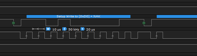
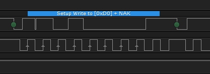
  Logic Analyzer Results

The code:

I2caRegs.I2CMDR.bit.IRS = 1;               // I2C enable


       // Make sure I2C is not busy and has stopped

       while (I2caRegs.I2CSTR.bit.BB == 1);       // busy loop

       I2caRegs.I2CSTR.bit.SCD = 1;               // Clear the SCD bit (stop condition bit)

       while(I2caRegs.I2CMDR.bit.STP == 1);       // stop bit loop


       I2caRegs.I2CSAR.bit.SAR = Slave_Adress;     // I2C slave address


       while (I2caRegs.I2CSTR.bit.BB == 1);       // still busy?


       //I2caRegs.I2CMDR.all = 0x2620;            // start, no stop bit, master, tx, reset I2C 00100110

       I2caRegs.I2CMDR.bit.NACKMOD = 0;           // NACK mode bit

       I2caRegs.I2CMDR.bit.FREE = 0;               // Stop I2C when suspended

       I2caRegs.I2CMDR.bit.STT = 1;              // START condition bit

       I2caRegs.I2CMDR.bit.STP = 1;               // STOP condition bit

       I2caRegs.I2CMDR.bit.MST = 1;               // Master mode

       I2caRegs.I2CMDR.bit.TRX = 1;               // Transmitter mode

       I2caRegs.I2CMDR.bit.XA = 0;                 // 7-bit addressing mode

       I2caRegs.I2CMDR.bit.RM = 0;                 // Nonrepeat mode

       I2caRegs.I2CMDR.bit.DLB = 0;               // Digital loopback mode is disabled

       I2caRegs.I2CMDR.bit.IRS = 1;               // The I2C module is enabled

       I2caRegs.I2CMDR.bit.STB = 0;               // The I2C module is not in the START byte mode

       I2caRegs.I2CMDR.bit.FDF = 0;               // Free data format mode is disabled

       I2caRegs.I2CMDR.bit.BC = 0;                 // 8 bits per data byte


       I2caRegs.I2CCNT     = 1;                   // assume register address is one byte


       while(I2caRegs.I2CSTR.bit.XRDY == 0);       // Do nothing till bus is free

       I2caRegs.I2CDXR.bit.DATA = Who_I_Am;       // register address of the sensor (1 byte)


       while(!I2caRegs.I2CSTR.bit.ARDY);           // all ready?


       //I2caRegs.I2CMDR.all = 0x2C20;             // start, stop bit when CNT =0, master, rx, reset I2C 00101100

       I2caRegs.I2CMDR.bit.NACKMOD = 0;           // NACK mode bit

       I2caRegs.I2CMDR.bit.FREE = 0;               // Stop I2C when suspended

       I2caRegs.I2CMDR.bit.STT = 1;               // START condition bit

       I2caRegs.I2CMDR.bit.STP = 1;               // STOP condition bit

       I2caRegs.I2CMDR.bit.MST = 1;               // Master mode

       I2caRegs.I2CMDR.bit.TRX = 0;               // Receiver mode

       I2caRegs.I2CMDR.bit.XA = 0;                 // 7-bit addressing mode

       I2caRegs.I2CMDR.bit.RM = 0;                 // Nonrepeat mode

       I2caRegs.I2CMDR.bit.DLB = 0;               // Digital loopback mode is disabled

       I2caRegs.I2CMDR.bit.IRS = 1;               // The I2C module is enabled

       I2caRegs.I2CMDR.bit.STB = 0;               // The I2C module is not in the START byte mode

       I2caRegs.I2CMDR.bit.FDF = 0;               // Free data format mode is disabled

       I2caRegs.I2CMDR.bit.BC = 0;                 // 8 bits per data byte


       I2caRegs.I2CCNT     = 1;                   // only read one byte data


       if(I2caRegs.I2CSTR.bit.NACK == 1)

       {

             I2caRegs.I2CSTR.all = I2C_CLR_NACK_BIT;   // 0x0002

       }


       I2caRegs.I2CMDR.bit.STP = 1;                   // stop bit when CNT=0


       Lucky_value   = I2caRegs.I2CDRR.bit.DATA;


i++;


When the breakpoint is placed next to the i ++ code line, the following result is observed:


If the breakpoint is not placed, the first images given is taken.

  • I guess the mentioned pictures can't show above. I'm attaching here also.

    These are Logic Analyzer result. 

    When the breakpoint is placed next to the i ++ code line, the following result is observed:


  • Hi Kadir,

    In your logic diagrams the slave address is being NAK'd each time. This means that 0xD0 does not match the MPU9250 9-DOF device slave address or that the slave device is not receiving properly.

    Do you have pin AD0 on your MPU9250 9-DOF device tied to GND to make the last bit of the slave address a zero? i.e. b1101000

    Does setting the I2C Free mode bit to 1 change the behavior at all?

           I2caRegs.I2CMDR.bit.FREE = 0;               // Stop I2C when suspended

    Best,

    Kevin

  • Hi Kevin,

    Thank you for your reply. Yes, I have a pin on my MPU9250 tied to GND.

    Also I have tried to change I2C free Mode bit to 1 and still same.

  • Hi Kadir,

    OK, then the MPU9250 isn't receiving and acknowledging the slave address properly.Where are you physically probing the I2C bus? Close to the master or slave device? Maybe try near the slave device if not already to make sure the data isn't getting corrupted before arriving there.

    Do you have pull-up resistors on the I2C lines, and what values?

    What I2C frequency are you operating at and does it meet the MPU9250 device's requirements? Maybe trying a slower clock speed will help.

    Best,

    Kevin

  • Hi Kevin,

    It's too close to the slave device and hence, there is no corrupted data before arriving the slave.

    Yes, there is a pull-up resistors with 10k ohm resistance, both SDA and SCL.

    Yes, I2C freq. meet the MPU9250 requirements and after you said, I tried the lower clock speed but nothing has been changed. 

  • Hi Kadir,

    I's hard to say what's going wrong, sorry I can't be of more help. It looks and sounds like the master to slave communication is working correctly, but the slave device is not responding to the slave address for some reason.

    The MPU9250 is 100% powered and hooked up to the C2000 board properly (maybe common grounding is an issue)? Can you reach out to TDK, who make the MPU9250, and see if they have any suggestions? I don't see any issues from the C2000 side.

    Best,

    Kevin