Other Parts Discussed in Thread: C2000WARE
Hi,
my customer debug the DCAN on F280049 with the help of SPRACE5.
In SPRACE5 page 4 with can_ex4_simple_transmit.c project they are expected to have waveform as shown in Figure3.
can_ex4_simple_transmit.c project is from:
C:\ti\c2000\C2000Ware_3_02_00_00\driverlib\f2837xs\examples\cpu1\can
They write their own code on F280049 code by imitating the example code and the file is attached, but they can only measure high on CANTx pin
Could you please help check where is wrong with the code? Thanks.
#include "F28004x_Device.h" // DSP28 Headerfile Include File
#include "F28004x_can.h"
//volatile struct CAN_REGS CanaRegs;
//volatile struct CAN_REGS CanbRegs;
UINT16 txMsgData[8];
void CAN_sendMessage(Uint16 Object);
void InitECan(void);
void main(void);
/*******************************************************************************
*Function name: InitECan()
*Description: This function initializes the eCAN module to a known state
*******************************************************************************/
void InitECan(void)
{
InitECanaGpio();
InitECana();
}
/*******************************************************************************
*Function name: InitECanaGpio()
*Description: This function initializes GPIO pins to function as eCAN pins
*******************************************************************************/
void InitECanaGpio(void)
{
EALLOW;
// Enable internal pull-up for the selected CAN pins
// Pull-ups can be enabled or disabled by the user.
// This will enable the pullups for the specified pins.
// Comment out other unwanted lines.
GpioCtrlRegs.GPAPUD.bit.GPIO4= 0; // Enable pull-up for GPIO30 (CANRXA)
GpioCtrlRegs.GPAPUD.bit.GPIO5 = 0; // Enable pull-up for GPIO31 (CANTXA)
// Set qualification for selected CAN pins to asynch only
// Inputs are synchronized to SYSCLKOUT by default.
// This will select asynch (no qualification) for the selected pins.
GpioCtrlRegs.GPAQSEL1.bit.GPIO5 = 3; // Asynch qual for GPIO30 (CANRXA)
// Configure eCAN-A pins using GPIO regs
// This specifies which of the possible GPIO pins will be eCAN functional pins.
GpioCtrlRegs.GPAMUX1.bit.GPIO4 = 0; // Configure GPIO30 for CANTXA operation
GpioCtrlRegs.GPAMUX1.bit.GPIO5 = 0; // Configure GPIO31 for CANRXA operation
GpioCtrlRegs.GPAGMUX1.bit.GPIO4 = 1; // Configure GPIO30 for CANTXA operation
GpioCtrlRegs.GPAGMUX1.bit.GPIO5 = 1; // Configure GPIO31 for CANRXA operation
GpioCtrlRegs.GPAMUX1.bit.GPIO4 = 2; // Configure GPIO30 for CANTXA operation
GpioCtrlRegs.GPAMUX1.bit.GPIO5 = 2; // Configure GPIO31 for CANRXA operation
EDIS;
}
void InitECana(void)
{
UINT32 i;
EALLOW;
CanaRegs.CAN_CTL.bit.Init = 1; // Idle, Configuration status(be used in Bit Timing and Message Ram Initialization)
CanaRegs.CAN_CTL.bit.PMD = 5; // Disable parity (��żУ��)
// CanaRegs.CAN_CTL.bit.DAR = 1; // Disable Automatic Retransmission (��ֹ�ش�)
EDIS;
// ��ʼ��can ͨ��ram �ռ�----------------------------------------------
/* CanaRegs.CAN_RAM_INIT.bit.CAN_RAM_INIT = 1;
CanaRegs.CAN_RAM_INIT.bit.KEY0 = 0;
CanaRegs.CAN_RAM_INIT.bit.KEY1 = 1;
CanaRegs.CAN_RAM_INIT.bit.KEY2 = 0;
CanaRegs.CAN_RAM_INIT.bit.KEY3 = 1;
*/
CanaRegs.CAN_RAM_INIT.all = 0x0000001AU;
while((CanaRegs.CAN_RAM_INIT.all & 0x003F) != 0x25)
{
// Wait until RAM Init is complete
}
// ��ʼ��can ͨ��ram �ռ����----------------------------------------------
EALLOW;
CanaRegs.CAN_CTL.bit.SWR = 1; // �������
EDIS;
// Delay for 14 cycles
// F28x_usDelay(1U);
for(i = 20; i > 0; i--)
{
;
}
CanaRegs.CAN_CTL.bit.CCE = 1; // Configuration Enable
// ������-------------------------------------------------
// clock = 100000000; // 100M Clock
// bitRate = 500000; // 500K bitrate
// bitTime = 20; // 20 can clock per bit
i = CanaRegs.CAN_CTL.all;
CanaRegs.CAN_CTL.bit.Init = 1;
CanaRegs.CAN_CTL.bit.CCE = 1;
/* CanaRegs.CAN_BTR.bit.BRP = 9; // brp = clock / (bitRate * bitTime) - 1 // Prescaler
CanaRegs.CAN_BTR.bit.SJW = 3;
CanaRegs.CAN_BTR.bit.TSEG1 = 10;
CanaRegs.CAN_BTR.bit.TSEG2 = 7;
CanaRegs.CAN_BTR.bit.BRPE = 0;
*/
CanaRegs.CAN_BTR.all = 0x00007AC9U;
if((i & 0x0001U) == 1)
{
CanaRegs.CAN_CTL.bit.Init = 0;
}
CanaRegs.CAN_CTL.bit.CCE = 0;
// ���ò����ʽ���------------------------------------------------
// ����IF1��IF2--------------------------------------------------------
while(CanaRegs.CAN_IF1CMD.bit.Busy == 1)
{
// Wait for busy bit to clear
}
// ���μĴ����������ã��ɶ�ID �ĵ�31 λȫ�����й��ˣ�ȡ��������
CanaRegs.CAN_IF1MSK.bit.MXtd = 0; // Extended Frame bit mask enable
CanaRegs.CAN_IF1MSK.bit.MDir = 0; // Direction bit mask enable
CanaRegs.CAN_IF1MSK.bit.Msk = 0x00000000; //0x000FFFFC; // 29 bit //IF1�Ƿ��ͣ���ʵ����Ҫ
// ID ���λΪ��Ч��־���ڶ�λ��չ֡������λ���䷽��
CanaRegs.CAN_IF1ARB.bit.MsgVal = 1;
CanaRegs.CAN_IF1ARB.bit.Xtd = 1; // extended frame
CanaRegs.CAN_IF1ARB.bit.ID = 0x95555555; // ��ʱ����ֵ
CanaRegs.CAN_IF1ARB.bit.Dir = 1; // transmit
// ���ƼĴ���
CanaRegs.CAN_IF1MCTL.bit.RmtEn = 0; // Disable Remote Message
CanaRegs.CAN_IF1MCTL.bit.UMask = 0; // Use Mask
CanaRegs.CAN_IF1MCTL.bit.DLC = 8; // Data Length = 8
CanaRegs.CAN_IF1MCTL.bit.EoB = 1;
CanaRegs.CAN_IF1MCTL.bit.RxIE = 0; // �����ж�ʹ�ܣ���������Ҫ�õ�
CanaRegs.CAN_IF1MCTL.bit.TxIE = 0;
// ����cmd �Ĵ������ɿ�����Ϣ�����Լ���������
CanaRegs.CAN_IF1CMD.bit.DIR = 1;
CanaRegs.CAN_IF1CMD.bit.Control = 1;
CanaRegs.CAN_IF1CMD.bit.Arb = 1;
CanaRegs.CAN_IF1CMD.bit.Mask = 1;
// ע�⣬д������Ż���������һ�δ���(IF1<-->Message Object)
CanaRegs.CAN_IF1CMD.bit.MSG_NUM = 5; // ����������5��������Ϣʱ�ٸ���
/* while(CanaRegs.CAN_IF1CMD.bit.Busy == 1)
{
// Wait for busy bit to clear
}
*/
txMsgData[0] = 0x01;
txMsgData[1] = 0x23;
txMsgData[2] = 0x45;
txMsgData[3] = 0x67;
txMsgData[4] = 0x89;
txMsgData[5] = 0xAB;
txMsgData[6] = 0xCD;
txMsgData[7] = 0xEF;
// Clear Init and CCE bits // ���CAN
CanaRegs.CAN_CTL.bit.Init = 0;
CanaRegs.CAN_CTL.bit.CCE = 0;
}
void CAN_sendMessage(Uint16 Object)
{
CanaRegs.CAN_IF1CMD.bit.Control = 1;
CanaRegs.CAN_IF1CMD.bit.MSG_NUM = Object;
// Wait for busy bit to clear
while(CanaRegs.CAN_IF1CMD.bit.Busy == 1)
{
;
}
CanaRegs.CAN_IF1DATA.bit.Data_0 = txMsgData[0];
CanaRegs.CAN_IF1DATA.bit.Data_1 = txMsgData[1];
CanaRegs.CAN_IF1DATA.bit.Data_2 = txMsgData[2];
CanaRegs.CAN_IF1DATA.bit.Data_3 = txMsgData[3];
CanaRegs.CAN_IF1DATB.bit.Data_4 = txMsgData[4];
CanaRegs.CAN_IF1DATB.bit.Data_5 = txMsgData[5];
CanaRegs.CAN_IF1DATB.bit.Data_6 = txMsgData[6];
CanaRegs.CAN_IF1DATB.bit.Data_7 = txMsgData[7];
// Write the data out to the CAN Data registers.
/*
// Set Data ready to be transferred from IF1 to message object
CanaRegs.CAN_IF1CMD.bit.DATA_A = 1; // Data
CanaRegs.CAN_IF1CMD.bit.DATA_B = 1;
// CanaRegs.CAN_IF1CMD.bit.Arb = 1; // Include ID
// CanaRegs.CAN_IF1CMD.bit.Control = 1; // Control bit Transmit
CanaRegs.CAN_IF1CMD.bit.DIR = 1; // Set Direction: Transmit
CanaRegs.CAN_IF1CMD.bit.TXRQST = 1; // Transmission Request
CanaRegs.CAN_IF1CMD.bit.MSG_NUM = Object; // = MailBox Number, and start transmission to message object
*/
CanaRegs.CAN_IF1CMD.all = 0x00870005;
}
void main(void)
{
DINT;
//ram initialize
InitRAM();
//Disable CPU interrupts and clear all CPU interrupt flags
IER = 0x0000;
IFR = 0x0000;
//Initialize PIE control registers:detail info in DSP280x_PieCtrl.c file
InitPieCtrl();
//Initialize PIE vector table with pointers to the shell ISR
InitPieVectTable();
InitGpio();
InitECan();
for(;;)
{
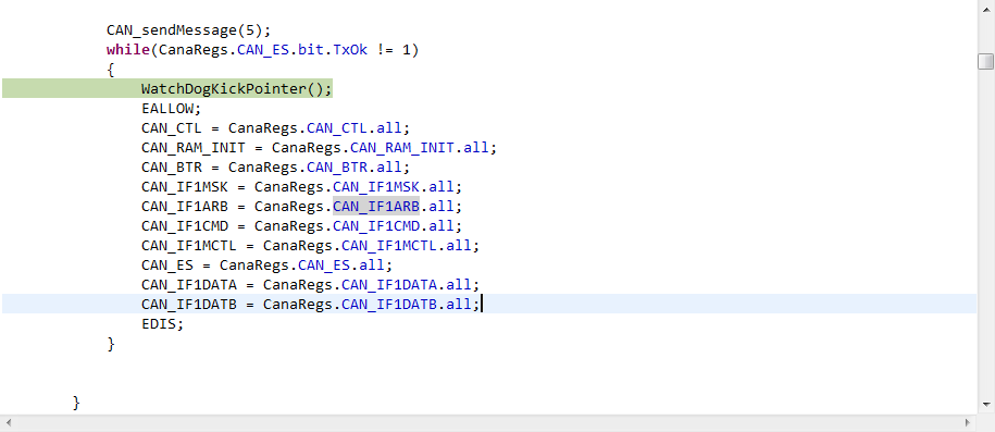
CAN_sendMessage(5);
while((CanaRegs.CAN_ES.all & 0x8000U) != 0x8000U)
{
WatchDogKickPointer();
}
}
}