


Other Parts Discussed in Thread: BOOSTXL-DRV8305EVM, CSD88599Q5DC, CSD88584Q5DC, MOTORWARE
There are 2 almost identical designs, one is working flawlessly another does not. Schematics of the working board are below:

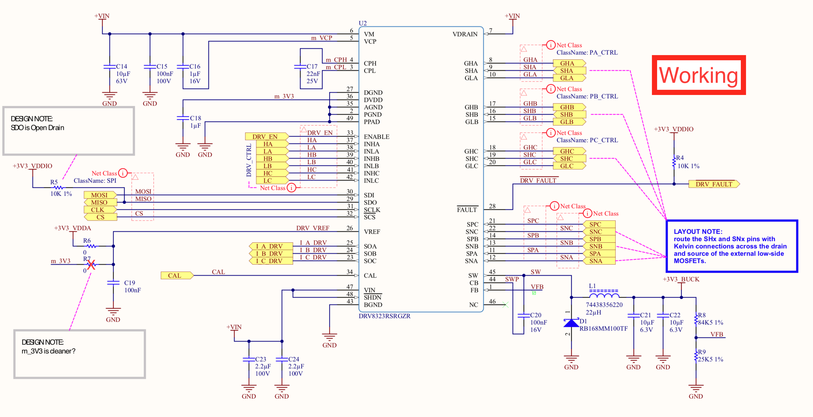
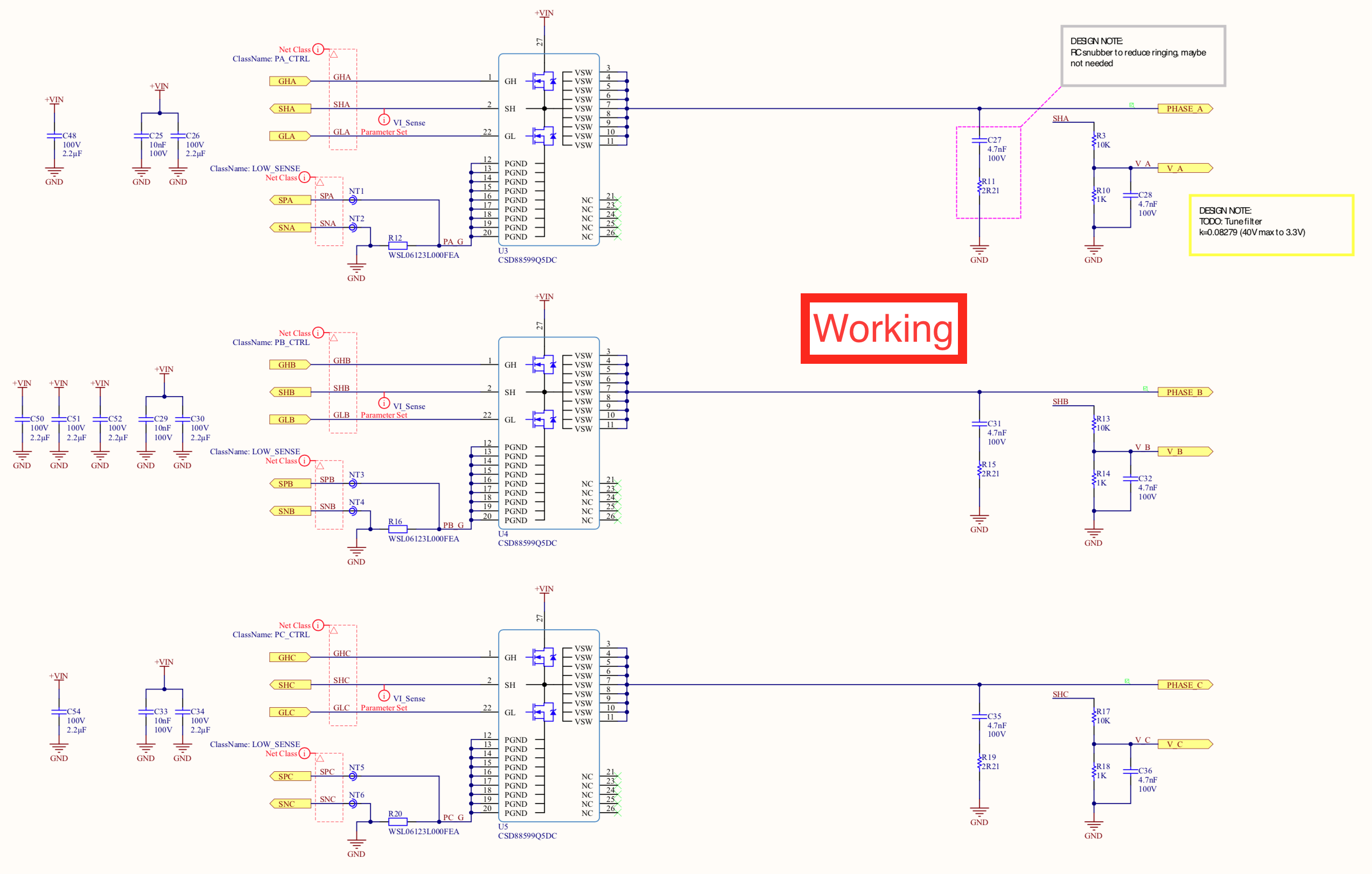
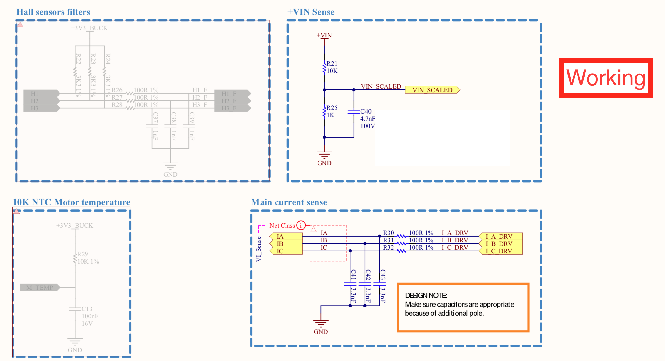
Compared to BOOSTXL-DRV8305EVM - filters on current feedback (ours 100R+3.3nF vs 56R+2.2nF), different voltage dividers ratio, wrong voltage filter cutoff frequency. Nevertheless it works great, even on 100RPM motor rotates smoothly and with a lot of torque available. user.h parameters used (learned on the boost board):
#define USER_IQ_FULL_SCALE_VOLTAGE_V      (24)
#define USER_ADC_FULL_SCALE_VOLTAGE_V     (33)
#define USER_IQ_FULL_SCALE_CURRENT_A      (41.25)
#define USER_ADC_FULL_SCALE_CURRENT_A     (55)
#define   I_A_offset    (0.287211)
#define   I_B_offset    (0.286317)
#define   I_C_offset    (0.284386)
#define   V_A_offset    (0.045690)
#define   V_B_offset    (0.045514)
#define   V_C_offset    (0.044920)
#define USER_SYSTEM_FREQ_MHz             (60.0)
#define USER_PWM_FREQ_kHz                (45.0)
#define USER_R_OVER_L_EST_FREQ_Hz (300)
#define USER_VOLTAGE_FILTER_POLE_Hz  (335.648)
#define USER_MOTOR_TYPE                 MOTOR_Type_Pm
#define USER_MOTOR_NUM_POLE_PAIRS       (7)
#define USER_MOTOR_Rr                   (NULL)
#define USER_MOTOR_Rs                   (0.0187090952)
#define USER_MOTOR_Ls_d                 (0.0000114935112)
#define USER_MOTOR_Ls_q                 (0.0000114935112)
#define USER_MOTOR_RATED_FLUX           (0.01622281)
#define USER_MOTOR_MAGNETIZING_CURRENT  (NULL)
#define USER_MOTOR_RES_EST_CURRENT      (6.0)
#define USER_MOTOR_IND_EST_CURRENT      (-6.0)
#define USER_MOTOR_MAX_CURRENT          (15.0)
#define USER_MOTOR_FLUX_EST_FREQ_Hz     (50)
user.h parameters learned on this board:
#define USER_IQ_FULL_SCALE_VOLTAGE_V      (24)
#define USER_ADC_FULL_SCALE_VOLTAGE_V (33.0)
#define USER_IQ_FULL_SCALE_CURRENT_A         (41.25)
#define USER_ADC_FULL_SCALE_CURRENT_A (27.5)
#define   I_A_offset    (0.287211)
#define   I_B_offset    (0.286317)
#define   I_C_offset    (0.284386)
#define   V_A_offset    (0.045690)
#define   V_B_offset    (0.045514
#define   V_C_offset    (0.044920)
#define USER_SYSTEM_FREQ_MHz             (60.0)
#define USER_PWM_FREQ_kHz                (45.0)
#define USER_R_OVER_L_EST_FREQ_Hz (300)
#define USER_VOLTAGE_FILTER_POLE_Hz  (335.648)
#define USER_MOTOR_TYPE                 MOTOR_Type_Pm
#define USER_MOTOR_NUM_POLE_PAIRS       (7)
#define USER_MOTOR_Rr                   (NULL)
#define USER_MOTOR_Rs                   (0.035178)
#define USER_MOTOR_Ls_d                 (0.000020464)
#define USER_MOTOR_Ls_q                 (0.000020464)
#define USER_MOTOR_RATED_FLUX           (0.010968)
#define USER_MOTOR_MAGNETIZING_CURRENT  (NULL)
#define USER_MOTOR_RES_EST_CURRENT      (6.0)
#define USER_MOTOR_IND_EST_CURRENT      (-6.0)
#define USER_MOTOR_MAX_CURRENT          (15.0)
#define USER_MOTOR_FLUX_EST_FREQ_Hz     (50)
Notice different USER_ADC_FULL_SCALE_CURRENT_A values, but either way motor spins very good, only id gives wrong results with 55A (around 10mR).
Not sure about USER_ADC_FULL_SCALE_CURRENT_A is it positive - negative current should be here (27.5 - -27.5 = 55A) or only the positive (27.5A).
Non working down below:
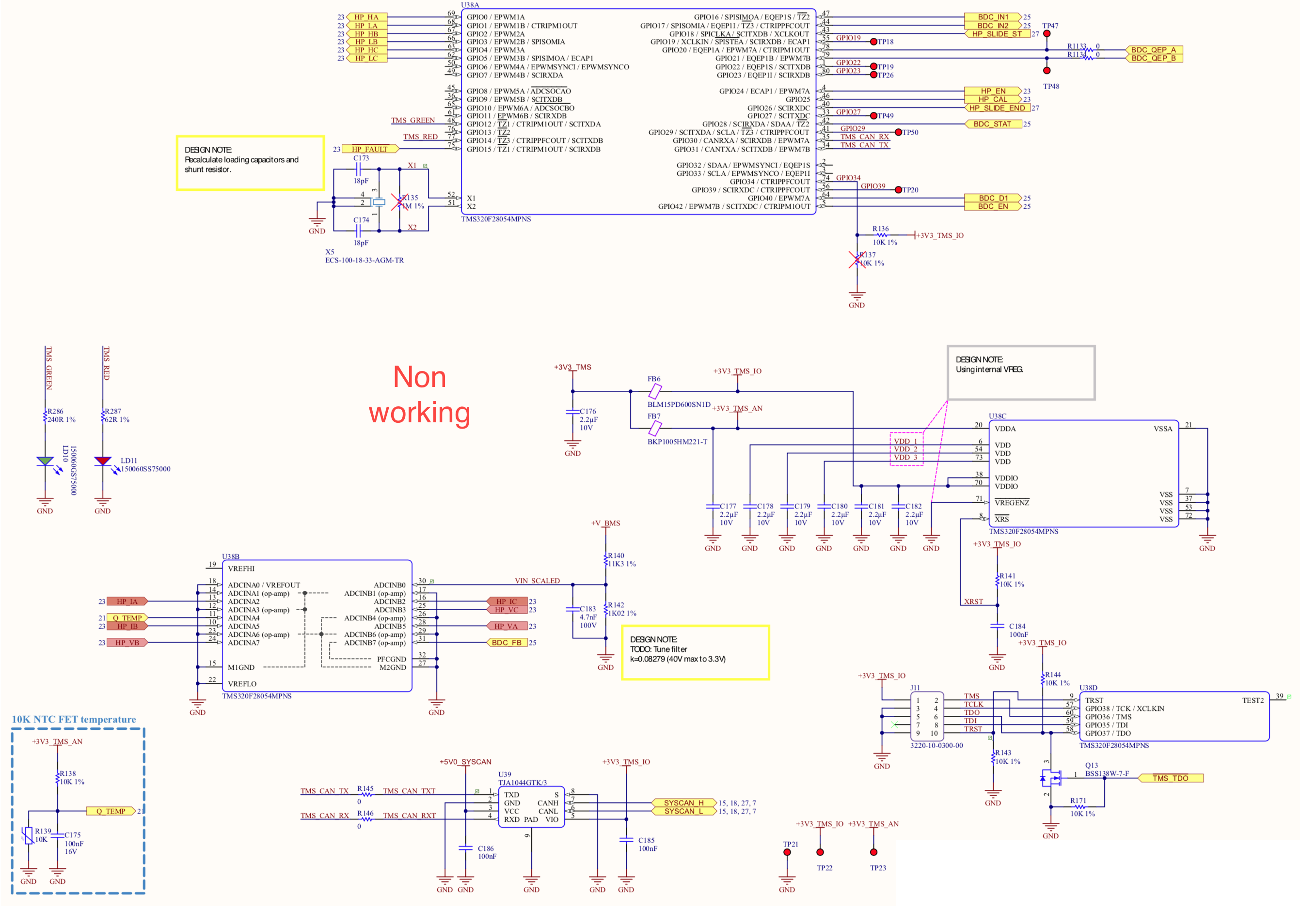
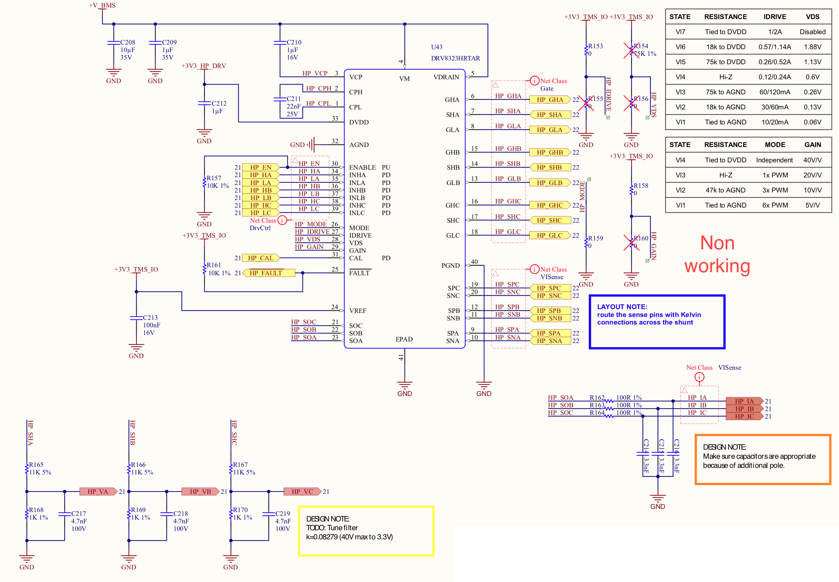

Differences that we know of:
1) CSD88584Q5DC (40V version) vs CSD88599Q5DC (60V version), would be very surprising if this is the problem.
2) DRV8323H (using same settings as in RS version by default) vs DRV8323RS (using default settings), can't think of any reason why would it matter that much.
3) Yet another voltage division ratio
4) Schematic show 40V/V gain, we tried both 40 and 20.
What we did:
1) Changed voltage dividers to 36K + 5K1 = 26.6V full scale, with higher full scale divider, learn was completing without errors, but with wrong results for Rs (around 10mR), flux in the region of (0.008V/Hz) and Ls (around 0.16mH). Now with the new dividers learn starts with a buzzing noise, gives out approximately 50mR, then slowly starts to rotate the motor. Right when the state machine moves from spin up to the Ls measurement motor suddenly stops and starts to spin again. With different values this stop is either pretty soft or with a hard click. After that it spins for a while and id ends with an error.
2) Changed voltage filter cutoff frequency to 356Hz, nothing changed, even though this seems to be important.
3) Connecting power almost directly to the FETs, on this board there is a bigger plane for ground and power, so that current flows below the DRV, potentially causing some problems, but nothing changed.
4) Changed USER_IQ_FULL_SCALE_VOLTAGE_V to many many different ones, without any noticeable changes, apart from the non starting code with some combinations.
5) Changed USER_IQ_FULL_SCALE_CURRENT_A back and worth, as we are not sure which value is correct.
6) Tried many USER_MOTOR_RES_EST_CURRENT, including 2A (around 10% of nominal current, id failed to spin the motor), 6A (used most of the time), 9A, 12A
7) Tried different USER_MOTOR_IND_EST_CURRENT currents -1, -1.5, -2, -6A
8) Tried different USER_MOTOR_FLUX_EST_FREQ_Hz, 20, 30, 40, 50, 100Hz. 20 is the worst, motor spins for a while and then produces horrible noise, other gives approximately the same results.
9) Tried different USER_R_OVER_L_EST_FREQ_Hz (100, 200, 300Hz), didn't notice any improvements.
10) Tried different motors, same behaviour on all of them.
11) Tried different bus voltages (12, 18, 24V), same behaviour on all voltages.
12) Tried using only ceramic capacitors and adding electrolytic 180uF (same as on working board), didn't noticed any changes.
13) Putting motor parameters from other boards and spinning the motor (always the same problem on slow rpms, sometimes on higher also).
14) Using lithium ion battery with short wires vs lab power supply and longer wires (working boards does not care, no noticeable changes here).
15) Verified that ADC is giving correct values (disabled all FETs, applied external voltage to each phase; enabled only low side FETs, applied 4A through electronic load; in both cases values where reasonable).
