This thread has been locked.

If you have a related question, please click the "Ask a related question" button in the top right corner. The newly created question will be automatically linked to this question.

WEBENCH® Tools/TMS320F28052F: TMS320F28052FPNQ

Part Number: TMS320F28052F
Other Parts Discussed in Thread: CONTROLSUITE, MOTORWARE

Tool/software: WEBENCH® Design Tools

Dear TI Team,

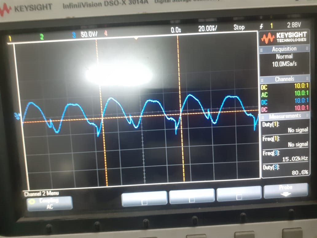
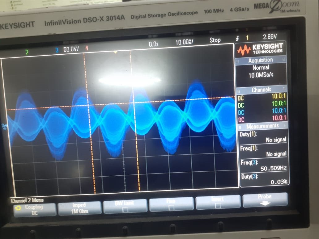
We are working on PMSM motor controller with TMS320F28052FPNQ. Hardware is ready but we are unable to run motor in upon loop. there is attached drive uotput waveform. may anyone suggest , how to operate  by 
  • Running in open loop requires to vary both voltage and frequency. I believe you are working with some controlsuite project. 

    If you installed TI's controlsuite, then refer to the user guide at 

    C:\ti\controlSUITE\development_kits\HVMotorCtrl+PfcKit_v2.1\HVPM_Enhanced_Sensorless_2803x\~Docs

    Best regards.

  • hi,

    We are using motorware. may you suggest some point or explain.

    Thanks 

  • You might refer to the following 3 documentations to modify the related parameters and device configuration codes in the files of hal.c, hal.h and user.h according to the hardware board. Make sure that the current and voltage sensing circuit of your own hardware board is good for running the motor.

    instaspin_labs.pdf at "\ti\motorware\motorware_1_01_00_18\docs\labs"

    motorware_hal_tutorial.pdf at "\ti\motorware\motorware_1_01_00_18\docs\tutorials"

    InstaSPIN-FOC™ and InstaSPIN-MOTION™ User's Guide http://www.ti.com/lit/ug/spruhj1h/spruhj1h.pdf 

    1. Change the PWM and ADC configuration in hal.c refer to the guide, motorware_hal_tutorial.pdf.

    2. Set correct parameters based on the hardware board in user.h

    #define USER_IQ_FULL_SCALE_VOLTAGE_V           (xx)

    #define USER_VOLTAGE_FILTER_POLE_Hz               (xx)

    #define USER_ADC_FULL_SCALE_VOLTAGE_V       (xx)

    #define USER_IQ_FULL_SCALE_CURRENT_A           (xx)

    #define USER_ADC_FULL_SCALE_CURRENT_A       (xx)


    3. make sure that the sign of the current coefficient in HAL_readAdcData() in hal.h matches the current sensing circuit. Refer to chapter 5.2.2 Current Feedback Polarity in InstaSPIN user's guide (SPRUHJ1H, http://www.ti.com/lit/ug/spruhj1h/spruhj1h.pdf) to set the sign of the current scale factor.


    static inline void HAL_readAdcData(HAL_Handle handle,HAL_AdcData_t *pAdcData)

    {

       _iq current_sf = HAL_getCurrentScaleFactor(handle);

    }


    4. Follow the instaSPIN lab guide to use lab01b and lab01c to verify your own hardware since you are not using the TI EVM kits and then you could run the subsequent labs.

    5. Using the lab02b or lab02c to identify the motor parameters, and use the identified parameters to run the motor

  • May you give support on call. It is very helpful for us. And please give your mail id . I will share some technical documents.

  • We would like to support such questions on E2E if it's not customer proprietary information. And could you please follow the guide above to check your hardware and settings in the project?