This thread has been locked.

If you have a related question, please click the "Ask a related question" button in the top right corner. The newly created question will be automatically linked to this question.

TMDSSOLARUINVKIT: TMDSSOLARUINVKIT: How to make it work.

Part Number: TMDSSOLARUINVKIT

Hi,

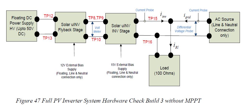
I have purchased this Solar Inverter Kit and am trying to make it work in Lab Environment. I have done the following steps so far:

1. Powered with 12 and 15V power supplies

2. Shorted TP8 and TP9

3. Connected a lab voltage supply (30V) between PV+ and PV-.

At this point, I was expecting to get a 110V output. But I am only able to measure ~100mVrms. What other steps do I need to follow. 

Also, I am not sure where to get the software to control the PCB, or which software to use as it did not come with any DVD or USB drives.


  • software for this design is in controlSUITE,https://www.ti.com/tool/CONTROLSUITE

    please follow the step by step guide 

    C:\ti\controlSUITE\development_kits\TMDSSOLARUINVKIT_v100\Docs

  • Thank you for the response. I was working with the ControlSuite software as you had suggested. Page 6 of the quick start guide for this part has the following instructions. Step 2 requires having GUI composer and I do not know where to find this program.

  • As controlSUITE is no longer maintained some of the features are not working due to changes in OS and windows etc.

    You will need to follow the UG not the QSG, 

  • Hi Manish,

    Thank you for the response. I am following your suggestion and am able to communicate with the equipment. I had a question about hooking up the equipment to the grid. Does connecting to the grid simply mean connecting the output of the inverter (TP15 and TP16) to a wall plug, or should it go to the main panel of the house?

    I am referring to the figure below when asking this question.


  • Anurag, 

    This design is meant to help you understand the system and is not a complete end equipment design, and only to be tested under lab environment.

    I will recommend testing it with AC source and emulated connection as described in the UG. 

    -Manish 

  • Thank you. I have a follow up question as I am still having an issue with the board to work. I am following instructions on page 32 of the User guide. I have set the Build = 1, MPPT = 0, Grid_Connect = 0.

    I have an 800 ohm resistor connected between TP8/9 and TP10and have connected a 50V power supply between TP12 and 13. Here is what I am seeing:

    1. The system is not drawing any current from the power supply.

    2. I follow instructions on page 34 of the UG and set the value of ClearFlyBacktrip = 1. However, when I do this the EPwm3Regs.TZFLG.all variable does not go to 0. Its value remains at 8

    3. I do not measure any significant voltage between TP8/9 and TP10. 

    I would appreciate any help in figuring this issue out.

    Thanks