This thread has been locked.

If you have a related question, please click the "Ask a related question" button in the top right corner. The newly created question will be automatically linked to this question.

TMS320F28027: Detecting Watchdog Reset

Part Number: TMS320F28027

 Hello!

I'd like to detect whether the last MCU reset was due to the watchdog or not. To do this, I'm inducing a watchdog reset (enabling the watchdog but never servicing it) when a UART message is received. I then try to detect the reset by checking that the WDFLAG bit == 1 in the WDCR register. However, this is never the case, even when I'm definitely resetting the MCU using the watchdog. Could there be something I'm missing? When enabling the watchdog, I also write a 1 to WDFLAG to clear the previously latched state. 

As an alternative to this, are there any writable registers that do not get cleared on a reset that can be used for such a purpose?

Thanks,

Aditya

  • Please refer to this link: http://e2e.ti.com/support/microcontrollers/c2000/f/171/t/826349


  • Hi Hareesh,

    Thanks for the additional info. While it was very helpful, it doesn't fully address what we're seeing. In our case, the WDFLAG is never set. I will be able to post a scope plot (hopefully on Monday) of the XRS pin at the time of the reset to verify the timing. 

    One part about your link that I'm confused on is whether the watchdog reset is expected to be detected if the XRS pin is left floating on our board. My understanding is that there is an internal pullup, but I don't know what the timing is on that. 

    Thanks,

    Aditya

  • In our case, the WDFLAG is never set.

    It is possible -XRS doesn’t rise quickly enough. Please post the scope capture of -XRS.


    One part about your link that I'm confused on is whether the watchdog reset is expected to be detected if the XRS pin is left floating on our board.

    If the pin is left floating, it should rise up very quickly and hence WD reset should be detected. Please post the schematics of the circuitry connected to the -XRS pin. You can send it privately to me through a Friendship request.


    My understanding is that there is an internal pullup, but I don't know what the timing is on that. 

    The internal PU is a weak PU. The value is given in the datasheet.

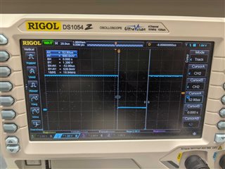
  • XRS line
    Here's a scope capture of a watchdog reset. Seems like the ~XRS line stays low for about 53us which should be quick enough to register as a watchdog reset. However, the 7th bit of WDCR (WDFLAG) is always 0. I also tried writing a (1<<7) to WDCR in case the latching behavior was impacting my reading but there was no change. Is there something I'm missing?

  • You should check the WDFLAG bit only after a delay; not right after a WD initiated reset. The following is very important and is from my other post: "Note that the WDFLAG is set only after (8192 * 4) OSCLK cycles from the time when the WDRST is de-asserted (goes high). Since WDRST is 512 OSCLK cycles wide, WDFLAG flag will be set ~3.7 mS after the start of WDRST (when it goes low)." If you read it too soon, you may not see the WDFLAG set. Go through the attached test case carefully.

    PIC_WD.c
    #include "DSP28x_Project.h"     // Device Headerfile and Examples Include File
    
    Uint16	i;
    volatile Uint16 j=0xdead;
    
    void main(void)
    {
    	EALLOW;
    	SysCtrlRegs.WDKEY = 0x0055;	
        SysCtrlRegs.WDKEY = 0x00AA;
    	SysCtrlRegs.WDCR = 0x0068;
    		
    	GpioCtrlRegs.GPAMUX1.all = 0;	
    	GpioCtrlRegs.GPADIR.bit.GPIO0 = 1;		// Configure as GPIO o/p
    	GpioCtrlRegs.GPADIR.bit.GPIO2 = 1;		// Configure as GPIO o/p	
    	GpioCtrlRegs.GPADIR.bit.GPIO4 = 1;		// Configure as GPIO o/p	
    	GpioDataRegs.GPADAT.bit.GPIO0 = 0;      // Drive low
    	GpioDataRegs.GPADAT.bit.GPIO2 = 0;      // Drive low  	
    	GpioDataRegs.GPADAT.bit.GPIO4 = 0;      // Drive low  
    
        for(i=0;i<32768;i++){ GpioDataRegs.GPATOGGLE.bit.GPIO4=1; }	// This provides the required delay for the WDFLAG bit to be set after a WD reset
        
        SysCtrlRegs.WDCR = 0x0028;				// Re-enable the WD - Note that WDFLAG is not cleared
    
    	if((SysCtrlRegs.WDCR & 0x0080)==0x0080)	// Is WDFLAG = 1? --> On all subsequent WD resets, this loop should be executed			  
    	{	SysCtrlRegs.WDCR = 0x00A8;						// CLEAR WDFLAG
    		for(;;)  {GpioDataRegs.GPATOGGLE.bit.GPIO0=1;}	// Toggle GPIO0, if WDFLAG = 1	
    	}
       
    	for(;;) { GpioDataRegs.GPATOGGLE.bit.GPIO2=1;	}	// This loop should be executed once and in the first iteration only
    														// Toggle GPIO2, if WDFLAG != 1			
    }
    
    
    //===========================================================================
    // No more.
    //===========================================================================
    
    /*
    If the code works correctly, only GPIO0 toggling should be observed..
    	
    0x0068 - Disable WD (w/o clearing WDFLAG)  	
    0x0028 - Enable  WD (w/o clearing WDFLAG)  	
    0x00A8 - Clear WDFLAG (w/o disabling WD)  		
    		
    	
    */


  • I'm currently polling the WDCR register over UART. It is possible that the first poll will be within 3.7ms, but subsequent ones will definitely not be. Should I still expect the WDFLAG not to be set by this point? 

    The material difference between my code and the example you posted is that I do not always enable the watchdog (line 23). Would there be a problem if I poll WDCR without enabling the watchdog?

  • WDFLAG will be set only after the aforementioned delay. Please run my testcase from Flash and you will see the correct results. 

    There is no problem polling the WDCR register when the WD is disabled. However, it needs to be enabled in order for it to timeout and set the WDFLAG bit. I just sent my code as a reference point. I had to write my code in a particular way to demonstrate the behavior of the WDFLAG bit.

  • On a related note, could you clarify what RAM is cleared by the watchdog reset or point me to such documentation please? This is likely a better way to resolve this for us because we can encode more information that just whether a watchdog reset occurred or not. 

  • A WD reset, by itself, does not disturb RAM contents.

  • THank you. In that case, we'll use a region of RAM to set flags when we need to reset and will address this more thoroughly when the watchdog reset needs to be tracked. 

  • OK. Be aware that certain newer C2000 devices include a RAM_INIT function in boot0RM that clears out certain RAM banks. Something to bear in mind when you migrate to newer C2000 devices.