This thread has been locked.

If you have a related question, please click the "Ask a related question" button in the top right corner. The newly created question will be automatically linked to this question.

BOOSTXL-BUCKCONV: ISR in the code not executing

Part Number: BOOSTXL-BUCKCONV
Other Parts Discussed in Thread: LAUNCHXL-F280025C, , TIDM-DC-DC-BUCK, POWERSUITE, C2000WARE, SYSBIOS, SFRA, LAUNCHXL-F280049C

I modified the example code based on F28004x  for BOOSTXL-BUCKCONV (in the TIDM-DC-DC-BUCK CONVERTER) to make it run on LAUNCHXL-F280025C. 

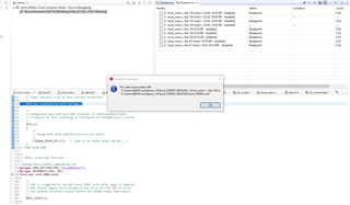
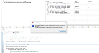
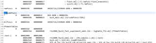
My problem is that the code is not running the ISR is the buck_main.c . As you can see in the image below, the breakpoint in line 159 shows the function there is not a part of the code compiled.

The ISR is below the line 159 and that also is not compiled.

Please help solve this issue asap. 

  • Ajit,

    I am going to assume for now that your project built and loaded without errors.  It could be that with optimization enabled, the compiler removed that specific line so the Breakpoint Manager is not able to find the exact instruction block at which to halt.

    Try setting a breakpoint on another instruction inside the BUCK_runIsr function, and/or see if disabling optimization is able to avoid this particular issue.

    -Tommy

  • Hi tlee,

    Thanks for the quick response. I guess the the optimization is turned off ( please see below to be sure).

    I do get a post-build error as below shown below (left image). Though I have not been able to solve this, the code does not give error while loading ( right image).


    I did put the breakpoint inside the Buck_Isr(). It shows the same message as below : 

  • Ajit,

    Did you baseline the software port using the buck project instead of the buck_nonpowerSUITE project? The post-build appears to be looking for powerSUITE elements that are not transferred over to your custom build.

    I see "-O3" in your build options, which should be the optimization setting.  You can find it here:

    -Tommy

  • Hi T Lee,

    After optimization off, I can atleast put breakpoints and it does not give the code not compiled error. However, the code still does not seem to run. I watched the EPWM TB Counter which is counting but the BUCK_isrEnter_ticks is 0 in the watch window. 

    For starting the project, I imported the buck_F28004x projected from Resource Explorer which I edited.

    Is there is different project available that is non-power SUITE? 

    -Ajit

  • Ajit,

    This is at least an improvement.

    I recommend inspecting the PIEIERn and PIEIFRn register bits associated with the interrupt trigger for the ISR in the Expression Window to see if they are ever set. You should also be able to poke the PIEIFRn bit while running to simulate the interrupt trigger and see if the ISR is executed in response.

    If this doesn't work, it might be some global interrupt setting or the vector table mapping. If it does work, it might be a module-level interrupt configuration issue.

    The non-powerSUITE project can be imported directly from the file system:  ~\C2000Ware_DigitalPower_SDK_XXXX\solutions\tidm_dc_dc_buck\f28004x\ccs\buck_nonpowerSUITE.projectspec

    I don't think you will have any functional problems with your current project; just the annoying warnings.

    -Tommy

  • Hi T Lee,

    The INT_ADCC1  is the trigger source for ISR. The PIEIFR bit is not set to 1. I am not able to toggle the PIEIFR bit from GUI.

    Also, since I am using INT_ADCC1 , should the VECT address be 0x0D44?

  • Ajit,

    According to the CPU Interrupt Vectors table from the F28002x TRM, the address of 0xD26 maps to the ILLEGAL Instruction (ITRAP) interrupt, so it's possible that the device landed there at some time.

    I see from PIEACK that Group 1 is waiting for an ACK. Try clearing it through the GUI by writing 1 to the bit while at a breakpoint.

    Also check the ADCC ADCINTFLG and ADCINTOVF registers to see if there is an overflow state.  The ADC will stop issuing triggers when it overflows.

    -Tommy

  • Hi T Lee,

    Is it possible that there is something wrong in linker file ?

    I made the following changes in one of the linker files I got from an example based on F28002x.Commented RAMLS5 and included address in RAMLS4_5 and replaced everywhere else

    /* Local shared RAM (CPU, HIC, BGCRC) */
    RAMLS4_5 : origin = 0x0000A000, length = 0x00001000 /* on-chip RAM block LS4 */
    //RAMLS5 : origin = 0x0000A800, length = 0x00000800 /* on-chip RAM block LS5 */
    RAMLS6_7 : origin = 0x0000B000, length = 0x00001000 /* on-chip RAM block LS6 */
    // RAMLS7 : origin = 0x0000B800, length = 0x00000800 /* on-chip RAM block LS7 */

    Earlier with the original file, the code was not building, but with the above modification, it now builds. Also,the PIE vector is correct now and the open loop VMC is correctly running up. 

    But still the ISR seems not running : Getting the same message of Code not associated. 

    I do see ADCINTOVF bit set  for ADCC_INT1. 

  • Ajit,

    Combining adjacent sections in the linker is valid, there is nothing wrong with doing that.  Did you port over all of the linker directives (like GROUP, LOAD, library sections, etc) from the F28004x example to F28002x?  Maybe the compiler cannot determine the proper placement for the ISR.

    -Tommy

  • Hi T Lee,

    I am using the  linker file from "Two Phase Interleaved LLC Resonant Converter" with only the above modifications.

    Below is the content of the file. Sorry I could not attach any file here, something is wrong.

    MEMORY

    {
    BEGIN : origin = 0x00080000, length = 0x00000002
    BOOT_RSVD : origin = 0x00000002, length = 0x00000126
    BOOT_RSVD_SYSBIOS: origin = 0x00000128, length = 0x00000080
    RESET : origin = 0x003FFFC0, length = 0x00000002

    /* RAM blocks */
    /* Dedicated RAM (CPU only) */
    RAMM0 : origin = 0x00000200, length = 0x00000200 /* on-chip RAM block M0 */
    RAMM1 : origin = 0x00000400, length = 0x00000400 /* on-chip RAM block M1 */

    /* Local shared RAM (CPU, HIC, BGCRC) */
    RAMLS4_5 : origin = 0x0000A000, length = 0x00001000 /* on-chip RAM block LS4 */
    //RAMLS5 : origin = 0x0000A800, length = 0x00000800 /* on-chip RAM block LS5 */
    RAMLS6_7 : origin = 0x0000B000, length = 0x00001000 /* on-chip RAM block LS6 */
    // RAMLS7 : origin = 0x0000B800, length = 0x00000800 /* on-chip RAM block LS7 */

    /* Global shared RAM (CPU, HIC, DMA) */
    RAMGS0 : origin = 0x0000C000, length = 0x00000800 /* on-chip RAM block GS0 */

    /* Flash sectors */
    /* BANK 0 */
    FLASH_BANK0_SEC0 : origin = 0x080002, length = 0x000FFE /* on-chip Flash */
    FLASH_BANK0_SEC1 : origin = 0x081000, length = 0x001000 /* on-chip Flash */
    FLASH_BANK0_SEC2 : origin = 0x082000, length = 0x001000 /* on-chip Flash */
    FLASH_BANK0_SEC3 : origin = 0x083000, length = 0x001000 /* on-chip Flash */
    FLASH_BANK0_SEC4 : origin = 0x084000, length = 0x001000 /* on-chip Flash */
    FLASH_BANK0_SEC5 : origin = 0x085000, length = 0x001000 /* on-chip Flash */
    FLASH_BANK0_SEC6 : origin = 0x086000, length = 0x001000 /* on-chip Flash */
    FLASH_BANK0_SEC7 : origin = 0x087000, length = 0x001000 /* on-chip Flash */
    FLASH_BANK0_SEC8 : origin = 0x088000, length = 0x001000 /* on-chip Flash */
    FLASH_BANK0_SEC9 : origin = 0x089000, length = 0x001000 /* on-chip Flash */
    FLASH_BANK0_SEC10 : origin = 0x08A000, length = 0x001000 /* on-chip Flash */
    FLASH_BANK0_SEC11 : origin = 0x08B000, length = 0x001000 /* on-chip Flash */
    FLASH_BANK0_SEC12 : origin = 0x08C000, length = 0x001000 /* on-chip Flash */
    FLASH_BANK0_SEC13 : origin = 0x08D000, length = 0x001000 /* on-chip Flash */
    FLASH_BANK0_SEC14 : origin = 0x08E000, length = 0x001000 /* on-chip Flash */
    FLASH_BANK0_SEC15 : origin = 0x08F000, length = 0x001000 /* on-chip Flash */

    BOOTROM : origin = 0x003F0000, length = 0x00008000
    BOOTROM_EXT : origin = 0x003F8000, length = 0x00007FC0

    }


    SECTIONS
    {
    codestart : > BEGIN
    .text : >> FLASH_BANK0_SEC2 | FLASH_BANK0_SEC3 | FLASH_BANK0_SEC4 | FLASH_BANK0_SEC5
    .cinit : > FLASH_BANK0_SEC1
    .init_array : > FLASH_BANK0_SEC1
    .switch : > FLASH_BANK0_SEC1
    .reset : > RESET TYPE = DSECT

    .data : > RAMM0
    .stack : > RAMM1

    .bss : > RAMLS4_5
    .sysmem : > RAMM0
    .const : > FLASH_BANK0_SEC5

    GROUP
    {
    .TI.ramfunc
    {
    -l sfra_f32_tmu_eabi.lib
    }
    ramfuncs
    isrcodefuncs
    dclfuncs
    }

    LOAD = FLASH_BANK0_SEC6,
    RUN = RAMLS6_7,
    LOAD_START(RamfuncsLoadStart),
    LOAD_SIZE(RamfuncsLoadSize),
    LOAD_END(RamfuncsLoadEnd),
    RUN_START(RamfuncsRunStart),
    RUN_SIZE(RamfuncsRunSize),
    RUN_END(RamfuncsRunEnd),
    ALIGN(4)

    SFRA_F32_Data : > RAMLS4_5, ALIGN = 64

    FPUmathTables : > FLASH_BANK0_SEC6

    .scratchpad : > RAMLS4_5
    controlVariables : > RAMLS4_5
    }

    /*
    //===========================================================================
    // End of file.
    //===========================================================================
    */

  • Hi T Lee,

    This is about SFRA  : I was doing Lab1 SFRA section. The Start Sweep button is greyed out as shown below. The COM port is connected. Could you please help on this too. 

    Thanks,

    Ajit

  • Ajit,

    Were you able to confirm that the ISR is executing? I would advise against trying to use SFRA until you are certain that the base software is running as expected. SFRA runs on top of the system so there are multiple sources for failure.

    With respect to the Code not associated message, you can inspect the .MAP file that is generated when you build the project to see where the ISR is code is being placed.  You can then use the Disassembly view to set a breakpoint there.  It can also be helpful to toggle a GPIO from the ISR and look for that activity while the system is running.

    -Tommy

  • Hi T Lee,

    Sorry I forgot to mention this before. To solve the ADCINTOVF bit set issue, I included below lines( yellow marked)  in the Buck_ISR function at the end of it.

    After this modification, I can now see the ISR running and the BUCK_isr_ticks updating values. 

    The map files shows the below location. 


  • Hi T Lee,

    Ideally, what should the order of clearing these interrupt flags: PIE ACK, clear ADCINTOVF and  clear ADCINTFLG. 

  • After this modification, I can now see the ISR running and the BUCK_isr_ticks updating values. 

    Good to hear that you finally have the ISR running.

    Ideally, what should the order of clearing these interrupt flags: PIE ACK, clear ADCINTOVF and  clear ADCINTFLG. 

    The hardware modules represented by these signals operate in parallel so the order of servicing doesn't matter as long as they are all cleared before the next interrupt from the same source is generated again.

    I should point out that the ADCINTOVF bits are designed to indicate a breakdown in real-time servicing of the interrupts. Some bits may be set during initialization if the system was abruptly restarted and a pending ADC interrupt was not serviced. However, you should not expect to see any asserted ADCINTOVF bits during normal operation.

    This is about SFRA  : I was doing Lab1 SFRA section. The Start Sweep button is greyed out as shown below. The COM port is connected. Could you please help on this too. 

    I'm not very familiar with this behavior. Can you start a new thread for this topic? It will be easier to bring in the SFRA expert.

  • "I should point out that the ADCINTOVF bits are designed to indicate a breakdown in real-time servicing of the interrupts. Some bits may be set during initialization if the system was abruptly restarted and a pending ADC interrupt was not serviced. However, you should not expect to see any asserted ADCINTOVF bits during normal operation."

    In the original code of 28004x, while initializing everything in the starting of main(), all the above 3 FLGs were cleared but inside the Buck_ISR, the ADCINTOVF was not cleared. Can this be a problem in light of what you just said?

    Thanks,

    Ajit

  • Ajit,

    Yes, I would be concerned about a system problem. It may be helpful to record the EPWM counter or add a GPIO toggle just after the interrupt flags are cleared in the ISR and then checking to see if an EPWM -> ADC SOC might be triggered before the flags are cleared.

    I also replied to this other post (with a fresh perspective) regarding BOOSTXL-BUCKCONV evaluation using F28002x: https://e2e.ti.com/support/microcontrollers/c2000/f/c2000-microcontrollers-forum/990152/boostxl-buckconv-migrate-buck-application-from-f280049c-to-f28002x-family

    I think the same recommendation would make sense here of using the native LAUNCHXL-F280049C is an option.

    -Tommy

  • Hi Tommy,

    Thank you very much. For now everything seems to work fine and I am able to run both open and closed loop. 

    For the closed loop PCMC, with the active load OFF , I am seeing VOUT as below. It is probably happening in the cases the inductor current is going negative.

    With active load enable and continuous load ( not negative IL), it is very good. 

    Could you please confirm if this does not happen in F280049x ? 

  • Ajit,

    I'm glad to hear that you are up and running.

    Yes, the PCMC output can become unstable when operating in discontinuous conduction mode. The TIDM-DC-DC-BUCK instructions call for enabling the continuous load for the PCMC labs.

    -Tommy

  • Hi Tommy,

    It is not really discontinuous mode, it is CCM operation with inductor current going negative. so this means the TF function of the loop is not changed. Do you have any idea why would it show this behavior ? The only thing that matters here is the peak of the inductor current for the trip which is a positive value. 

  • Ajit,

    I am not an expert in power conversion theory so I would recommend seeking information or research in the public domain for analysis.

    My understanding is that the converter is considered to be in DCM when the inductor becomes 0A or negative, and the transfer function is different between the two modes so there can be discontinuities as the converter moves between CCM and DCM.

    -Tommy