This thread has been locked.

If you have a related question, please click the "Ask a related question" button in the top right corner. The newly created question will be automatically linked to this question.

TMS320F28377D-EP: Performance issue

Part Number: TMS320F28377D-EP
Other Parts Discussed in Thread: C2000WARE

Hi,

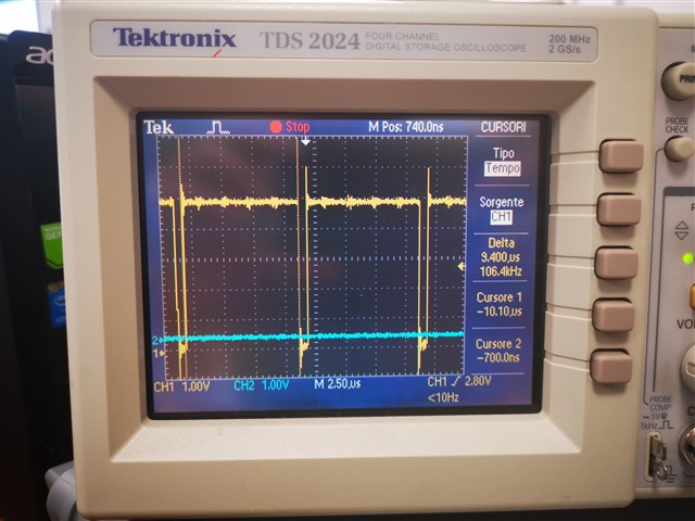
I'm facing a really strange problem on my application. Basically in my app there are 4 EPWM where the pwm#3 triggers ADCs. I decided to measure the occupation time for every single ADC by strobing a GPIO but the stuff I was seeing in oscilloscope was totally different from my expectations.

So I decided to drive the same strobe on main.c (basically an empty main) to check the timing and now the trouble begin.

On this main.c the frequency measured with o-scope is 1.64MHz (but my clock is 100Mhz and I'm only doing 200 sums)

    /* Check RAM */
    ramCheck(); /* does nothing */

    /* Init variables (must be at the code beginning) */
    CSU_initVariables();

    /* Low level inits */
    CSU_InitBoot();
    GPIO_InitSafe(); /* does nothing */

    duty = 0.5F;
    flagConvertTemp = 0;

    debugLength = 0;

    startMagazzino = 1;

    int i = 0;
    marco1 = 0;
    while (1)
    {
        GpioDataRegs.GPATOGGLE.bit.GPIO25 = 1;
        for (i = 0; i < 200; i++)
        {
            marcoDebug += 10;
        }

        marco1 = 0;
        switch (marco1)
        {
        case 1:
            marco1 = 0;
            CSU_SetPWMDuty(1, duty);
            CSU_SetPWMDuty(2, duty);
            CSU_SetPWMDuty(3, duty);
            CSU_SetPWMDuty(4, duty);
            break;
        default:
            break;
        }

    }
}

But on this main.c the frequecy is only 7.8KHz (but all the settings are the same)

int32_t main(void)
{

    GPIOSTATUS prova;
    /* Check RAM */
    ramCheck(); /* does nothing */

    /* Init variables (must be at the code beginning) */
    CSU_initVariables();

    /* Low level inits */
    CSU_InitBoot();
    GPIO_InitSafe(); /* does nothing */

    duty = 0.5F;
    flagConvertTemp = 0;

    debugLength = 0;

    startMagazzino = 1;

    int i = 0;
    marco1 = 0;
    while (1)
    {
        GpioDataRegs.GPATOGGLE.bit.GPIO25 = 1;
        for (i = 0; i < 200; i++)
        {
            marcoDebug += 10;
        }

        //marco1 = 0;
        switch (marco1)
        {
        case 1:
            marco1 = 0;
            CSU_SetPWMDuty(1, duty);
            CSU_SetPWMDuty(2, duty);
            CSU_SetPWMDuty(3, duty);
            CSU_SetPWMDuty(4, duty);
            break;
        default:
            break;
        }

    }
}

I only commented out the line 32, but the code never reaches the "case 1" of the switch becouse the variable is set to 0 on top and no-one changes it so I was expecting no difference at all instead of having a frequency drammatically lowered.

I don't know what could be the problem and I also tried to optimize from the Project --> Properties-->Optimization but nothing.

Seems some kind of memory issue or linker issue or project properties issue and I'm available to share the entire project in PM for further analysis. 

P.s. I'm pretty sure the cpu clock from pll is 100MHz because I measured the PWM frequency and it is as expected

Thanks,

M.

  • Hi Marco,

    the stuff I was seeing in oscilloscope was totally different from my expectations.

    How different was what you were expecting from what you were seeing?

    I only commented out the line 32

    This is the only difference in the two main.c files? Have you tried to run the example project for gpio_toggle and see if that works for you?,  C:\ti\c2000\C2000Ware_version\driverlib\f2837xd\examples\cpu1\gpio

    If the example project works for you, then I would compare project settings and slowly add functionality from your main.c file to identify what the issue might be.

    Best Regards,
    Marlyn

  • I was expecting a toggle frequency at the order of MHzs, but I was measuring a frequency of a bunch of KHz that is strange, because main does not do anything, in theory.

    Yes, it was the only difference. I did the two tests only commenting out that instruction. Now I try the example you provided and check the settings. 

    Is there a way to export all the project settings from one project to another or have I to do it manually?

    Thanks,

    M. 

  • Ok I just built a project from skratch, but measuring the execution time seems not correct.

    I trigger ADC1, ADC2 from EPWM3 running @100KHz.

    Inside the adc ISRs I perform the calibrations in order to decode the ADC registers but if I measue from start of ADC1 ISR to the end of ADC2 ISR the total time is around 9 microS. (See pic below). Please note than ADCs are triggered @10microS, so 90% only for a bunch of multiplications seems a lot of time.

    The priority is ADC 1 and then ADC2 and it is correct because I'm measuring from SET to CLEAR of GPIO.

    Here is the code:

    Setup pie vector table:

    uint32_t (*dest)[] = { 0U };
    int i = 0;
    
    dest = (void*) &PieVectTable;
    
    /* set INTM register bit to disable interrupts */
    CORE_SIntmext();
    
    /* disable vector fetching from ePIE block */
    PieCtrlRegs.PIECTRL.bit.ENPIE = PIECTRL_DISABLE;
    
    /* clear all PIEIER registers: */
    PieCtrlRegs.PIEIER1.all = PIEIER_DISABLE;
    PieCtrlRegs.PIEIER2.all = PIEIER_DISABLE;
    PieCtrlRegs.PIEIER3.all = PIEIER_DISABLE;
    PieCtrlRegs.PIEIER4.all = PIEIER_DISABLE;
    PieCtrlRegs.PIEIER5.all = PIEIER_DISABLE;
    PieCtrlRegs.PIEIER6.all = PIEIER_DISABLE;
    PieCtrlRegs.PIEIER7.all = PIEIER_DISABLE;
    PieCtrlRegs.PIEIER8.all = PIEIER_DISABLE;
    PieCtrlRegs.PIEIER9.all = PIEIER_DISABLE;
    PieCtrlRegs.PIEIER10.all = PIEIER_DISABLE;
    PieCtrlRegs.PIEIER11.all = PIEIER_DISABLE;
    PieCtrlRegs.PIEIER12.all = PIEIER_DISABLE;
    
    /* clear all PIEIFR registers: */
    PieCtrlRegs.PIEIFR1.all = PIEIFR_DISABLE;
    PieCtrlRegs.PIEIFR2.all = PIEIFR_DISABLE;
    PieCtrlRegs.PIEIFR3.all = PIEIFR_DISABLE;
    PieCtrlRegs.PIEIFR4.all = PIEIFR_DISABLE;
    PieCtrlRegs.PIEIFR5.all = PIEIFR_DISABLE;
    PieCtrlRegs.PIEIFR6.all = PIEIFR_DISABLE;
    PieCtrlRegs.PIEIFR7.all = PIEIFR_DISABLE;
    PieCtrlRegs.PIEIFR8.all = PIEIFR_DISABLE;
    PieCtrlRegs.PIEIFR9.all = PIEIFR_DISABLE;
    PieCtrlRegs.PIEIFR10.all = PIEIFR_DISABLE;
    PieCtrlRegs.PIEIFR11.all = PIEIFR_DISABLE;
    PieCtrlRegs.PIEIFR12.all = PIEIFR_DISABLE;
    
    /* reset interrupt enable register */
    IER = 0;
    
    /* reset interrupt flag register */
    IFR = 0;
    
    EALLOW;
    
    for (i = 3; i < 227; i++)
    {
    (*dest)[i] = 0;
    }
    
    EDIS;
    
    /* enable vector fetching from ePIE block */
    PieCtrlRegs.PIECTRL.bit.ENPIE = PIECTRL_ENABLE;
    
    /* enable writing to protected CPU registers */
    EALLOW;
    
    /* initialize PIE vector table. This enables the interrupts service routines
    * for CPU timer 1 */
    PieVectTable.ADCA1_INT = &CSU_adc1_isr;
    PieVectTable.ADCB1_INT = &CSU_adc2_isr;
    PieVectTable.ADCC1_INT = &CSU_adc3_isr;
    PieVectTable.ADCD1_INT = &CSU_adc4_isr;
    IER = M_INT1 | M_INT13; /* Timer and ADC */
    /* Enable ADCA1 in the PIE: Group 1 interrupt 1 */
    PieCtrlRegs.PIEIER1.bit.INTx1 = 1;
    /* Enable ADCA2 in the PIE: Group 1 interrupt 2 */
    PieCtrlRegs.PIEIER1.bit.INTx2 = 1;
    /* Enable ADCA3 in the PIE: Group 1 interrupt 2 */
    PieCtrlRegs.PIEIER1.bit.INTx3 = 1;
    /* Enable ADCA4 in the PIE: Group 1 interrupt 6 */
    PieCtrlRegs.PIEIER1.bit.INTx6 = 1;
    EDIS;
    Interrupts:

    #pragma CODE_SECTION(CSU_adc1_isr, ".TI.ramfunc");
    __interrupt void CSU_adc1_isr(void)
    {
    
    uint16_t TempPIEIER;
    uint8_t pippo;
    static volatile uint32_t dummy;
    static volatile uint32_t dummy1;
    
    TempPIEIER = PieCtrlRegs.PIEIER1.all;
    
    CORE_Eallowext();
    
    IER |= M_INT1;
    IER &= M_INT1;
    
    PieCtrlRegs.PIEIER1.all &= 0x0001;
    PieCtrlRegs.PIEACK.all = 0xFFFF;
    CORE_NOP();
    EINT;
    
    AdcaRegs.ADCINTFLGCLR.bit.ADCINT1 = 1; /* Clear the flag to generate other interrupts on SOC */
    
    if (1 == AdcaRegs.ADCINTOVF.bit.ADCINT1)
    {
    AdcaRegs.ADCINTOVFCLR.bit.ADCINT1 = 1; /* clear INT1 overflow flag */
    AdcaRegs.ADCINTFLGCLR.bit.ADCINT1 = 1; /* clear INT1 flag */
    }
    
    PieCtrlRegs.PIEACK.all = PIEACK_GROUP1;
    
    GpioDataRegs.GPASET.bit.GPIO25 = 1;
    
    calibs.cpu_sens_iin_instant = (float32_t) (AdcaResultRegs.ADCRESULT0 * IIN_CAL);
    calibs.cpu_sens_vin_instant = (float32_t) (AdcaResultRegs.ADCRESULT1 * VIN_CAL);
    calibs.cpu_sens_illc_instant = (float32_t) ((AdcaResultRegs.ADCRESULT2 - VMID) * ILLC_CAL) / ADC_BIT;
    calibs.cpu_sens_vdclink_algo1 = (float32_t) (AdcaResultRegs.ADCRESULT3 * VCAL_DCLINK);
    calibs.cpu_sens_idclink_algo1 = (float32_t) (AdcaResultRegs.ADCRESULT4 * IDC_CAL) / ADC_BIT;
    
    /* Exit ISR */
    DINT;
    PieCtrlRegs.PIEIER1.all = TempPIEIER;
    EDIS;
    semaphore = 0;
    
    }
    
    
    #pragma CODE_SECTION(CSU_adc2_isr, ".TI.ramfunc");
    __interrupt void CSU_adc2_isr(void)
    {
    
    volatile uint32_t dummy;
    uint16_t TempPIEIER;
    
    TempPIEIER = PieCtrlRegs.PIEIER1.all;
    
    CORE_Eallowext();
    
    IER |= M_INT1;
    IER &= M_INT1;
    
    PieCtrlRegs.PIEIER1.all &= 0x0002;
    PieCtrlRegs.PIEACK.all = 0xFFFF;
    CORE_NOP();
    EINT;
    
    AdcbRegs.ADCINTFLGCLR.bit.ADCINT1 = 1; /* Clear the flag to generate other interrupts on SOC */
    
    if (1 == AdcbRegs.ADCINTOVF.bit.ADCINT1)
    {
    AdcbRegs.ADCINTOVFCLR.bit.ADCINT1 = 1; /* clear INT1 overflow flag */
    AdcbRegs.ADCINTFLGCLR.bit.ADCINT1 = 1; /* clear INT1 flag */
    }
    
    PieCtrlRegs.PIEACK.all = PIEACK_GROUP1;
    
    calibs.cpu_sens_vout_instant_prec = calibs.cpu_sens_vout_instant;
    
    calibs.cpu_sens_idclink_algo2 = (float32_t) ((AdcbResultRegs.ADCRESULT0 * IDC_CAL) / ADC_BIT);
    calibs.cpu_sens_vdclink_algo2 = (float32_t) (AdcbResultRegs.ADCRESULT1 * VCAL_DCLINK);
    calibs.cpu_sens_iout_instant = (float32_t) (IOUT_CAL * (AdcbResultRegs.ADCRESULT2 - VMID)) / ADC_BIT;
    calibs.cpu_sens_vout_instant = (float32_t) (VOUT_CAL * (AdcbResultRegs.ADCRESULT3 - VMID)) / ADC_BIT;
    
    GpioDataRegs.GPACLEAR.bit.GPIO25 = 1;


    /* Exit ISR */
    DINT;
    PieCtrlRegs.PIEIER1.all = TempPIEIER;
    EDIS;
    
    }


    Finally the PLLCLK is maximum 200MHz and it is confirmed because if I measure PWM frequency (and ADC trigger frequency) is exactly 100KHz. PWM prescaler is 2 and period = 500 up and down so 200000000Hz/2000 = 100 000Hz.

    I'm really not understanding what's going on. Any help? Is it normal?

    Regards,

    M.

  • Hi Marco,

    It appears that you are setting the gpio half way through the ISR for ADC1 and towards the end of ADC2 ISR. There are a lot of other things going on during this time though not just multiplications. There is ISR entry time and exit time to account for, acknowledging the ISR, etc. I would encourage you to look at each ISR itself (gpio set at the very beginning and then clear at the end). If your concern is the duration length of each ISR, try to identify what takes the most time within each ISR by changing the location of your gpio clear instruction.

    Best Regards,

    Marlyn 

  • Hi,

    thanks for the replies. Thanks for the approach.

    I measured the times and it turned out that the extra-time is from end of exit of adc isr and start of entry of adc2 isr. The timings are below:

    T CALC ISR1 = 220nS
    T CALC ISR2 = 220nS
    
    t exit isr1 = 90 ns
    t exit isr2 = 90 ns
    
    t start isr1 = 220 ns
    t start isr2 = 220 ns
    
    end of exit isr1 to start of entry isr2 = 8800ns --> (with acqps = 20)

    The timing are pretty repetitive so I guess there are no issues about the setup of measures.

    An other thing I've noticed is that changing the ACQPS, the time 8800ns remains the same.

    The ADC1 and 2 are configured in trigger from EPWM3 SOCA (100KHz = 10000ns) so I'm not understanding that 88% of total time.

    I believe I was configuring ADCs well, but evidently there's some issue. Here is the code of the ADCs configuration:

    EALLOW;
    /* Enable peripheral clock */
    CpuSysRegs.PCLKCR13.bit.ADC_A = 1;
    CpuSysRegs.PCLKCR13.bit.ADC_B = 1;
    
    DevCfgRegs.SOFTPRES13.bit.ADC_A = 1;
        DevCfgRegs.SOFTPRES13.bit.ADC_B = 1;
        delay();
        DevCfgRegs.SOFTPRES13.bit.ADC_A = 0;
        DevCfgRegs.SOFTPRES13.bit.ADC_B = 0;
    
        AdcSetMode(0, ADC_RESOLUTION_12BIT, 0);
        AdcSetMode(1, ADC_RESOLUTION_12BIT, 0);
        AdcaRegs.ADCCTL2.bit.PRESCALE = 4;
        AdcbRegs.ADCCTL2.bit.PRESCALE = 4;
        
        /* 3- Power up the ADC*/
        AdcaRegs.ADCCTL1.bit.ADCPWDNZ = 1;
        AdcbRegs.ADCCTL1.bit.ADCPWDNZ = 1;
        delay();
        
        AdcaRegs.ADCSOC0CTL.bit.CHSEL = 0;
        AdcaRegs.ADCSOC0CTL.bit.ACQPS = 63; // 320nS minimum allowed
        AdcaRegs.ADCSOC0CTL.bit.TRIGSEL = 9; /* EPW3 ADC SOC A */
    
        AdcaRegs.ADCSOC1CTL.bit.CHSEL = 1;
        AdcaRegs.ADCSOC1CTL.bit.ACQPS = 63;
        AdcaRegs.ADCSOC1CTL.bit.TRIGSEL = 9; /* EPWM3 ADC SOC A */
    
        AdcaRegs.ADCSOC2CTL.bit.CHSEL = 2;
        AdcaRegs.ADCSOC2CTL.bit.ACQPS = 63;
        AdcaRegs.ADCSOC2CTL.bit.TRIGSEL = 9; /* EPWM3 ADC SOC A */
    
        AdcaRegs.ADCSOC3CTL.bit.CHSEL = 3;
        AdcaRegs.ADCSOC3CTL.bit.ACQPS = 63;
        AdcaRegs.ADCSOC3CTL.bit.TRIGSEL = 9; /* EPWM3 ADC SOC A */
    
        AdcaRegs.ADCSOC4CTL.bit.CHSEL = 4;
        AdcaRegs.ADCSOC4CTL.bit.ACQPS = 63;
        AdcaRegs.ADCSOC4CTL.bit.TRIGSEL = 9; /* EPWM3 ADC SOC A */
    
        AdcaRegs.ADCINTSEL1N2.bit.INT1SEL = 4; /* Interrupt generated at EOC4 */
        AdcaRegs.ADCSOCPRICTL.bit.SOCPRIORITY = 5;
        AdcaRegs.ADCINTSEL1N2.bit.INT1E = 1; /* interrupt enable */
        AdcaRegs.ADCINTSEL1N2.bit.INT1CONT = 0; /* no further interrupt until clear */
        
        AdcbRegs.ADCSOC0CTL.bit.CHSEL = 0;
        AdcbRegs.ADCSOC0CTL.bit.ACQPS = 63;
        AdcbRegs.ADCSOC0CTL.bit.TRIGSEL = 9; /* EPW3 ADC SOC A */
    
        AdcbRegs.ADCSOC1CTL.bit.CHSEL = 1;
        AdcbRegs.ADCSOC1CTL.bit.ACQPS = 63;
        AdcbRegs.ADCSOC1CTL.bit.TRIGSEL = 9; /* EPWM3 ADC SOC A */
    
        AdcbRegs.ADCSOC2CTL.bit.CHSEL = 2;
        AdcbRegs.ADCSOC2CTL.bit.ACQPS = 63;
        AdcbRegs.ADCSOC2CTL.bit.TRIGSEL = 9; /* EPWM3 ADC SOC A */
    
        AdcbRegs.ADCSOC3CTL.bit.CHSEL = 3;
        AdcbRegs.ADCSOC3CTL.bit.ACQPS = 63;
        AdcbRegs.ADCSOC3CTL.bit.TRIGSEL = 9; /* EPWM3 ADC SOC A */
    
        AdcbRegs.ADCINTSEL1N2.bit.INT1SEL = 3; /* interrupt at EOC3 */
        AdcbRegs.ADCSOCPRICTL.bit.SOCPRIORITY = 4;
        AdcbRegs.ADCINTSEL1N2.bit.INT1E = 1; /* interrupt enable */
    
        EDIS;
     

    Thanks for your time,

    M.

    EDIT: It was my error in measuring times and understanding ADCs.

    I didn't take into account that  ADCB is faster than ADCA (ADCA is 5 channels and ADCB is 4 channels) and the interrupt B comes first.

    I was measuring from A to B instead of B to A. Measuring from B to A now works as expected.