This thread has been locked.

If you have a related question, please click the "Ask a related question" button in the top right corner. The newly created question will be automatically linked to this question.

TMDSHVMTRINSPIN: PMSM motor with full load

Part Number: TMDSHVMTRINSPIN
Other Parts Discussed in Thread: TMS320F280049C, , C2000WARE, BOOSTXL-DRV8320RS, OPA2350, AMC1300

Hello team,
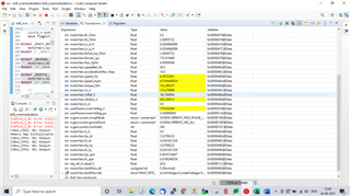
We are using TMDSHVMTRINSPIN + TMS320F280049C, earlier we could control the motor without load, by flashing the codes presented ‘C:\ti\c2000\C2000Ware_MotorControl_SDK_3_00_01_00\solutions\tmdshvmtrinspin\f28004x\ccs\sensorless_foc ".for speed controlling we are using lab07.
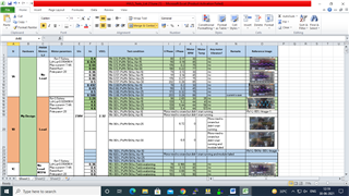
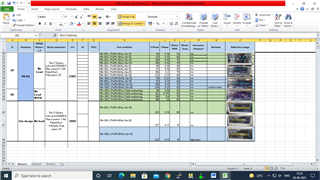
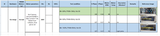
1. Now we are going to test my motor with load, below are my motor parameters
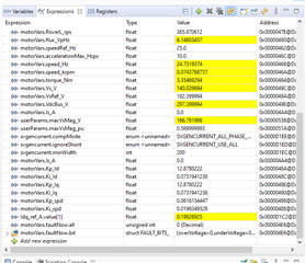
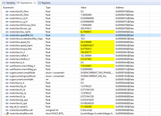
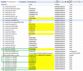
Rs: 6.5ohm
Ld:  0.010496
Lq: 0.010496
Pole pains: 20
Rated Torque: 230 N-m
Output power: 1.4 KW
2.Is TMDSHVMTRINSPIN that board support to test my motor with full load?
My application is HVLS fan
FYI: we are using lab05 for motor parameters identification, we don’t have any problem without load condition. we get correct parameters.

thank you

  • The hardware is rated for 750w when fed from ac mains. There's provision to directly feed DC (external power supply) to the inverter in which case the output power can be increased to 1KW. Refer to page 7 of  Hardware Quick Start Guide for more info. 

  • Hi thanks for the reply,
    We follow the reference guide provided in the below path"
    C:\ti\c2000\C2000Ware_MotorControl_SDK_3_00_01_00\solutions\tmdshvmtrinspin\docs\qsg_hw_hvmtr_r1p1"
    in the above document page 6 it shown that maximum load is 1.5KW,input to inverter is 350Vdc.

    thank you

  • Please look at the conditions specified in page 7 for power capability: Replicated below for easy reference. Unmodified HW (no changes to heatsink and Fan) can only support 1KW at room temperature. Any higher ambient temperature or higher power would need larger heatsink (lower thermal resistance) and larger Fan (still not exceeding 1.5KW output power)

    *All the power rating tests for the power stages have been performed at room temperature. The motor stage is rated for
    1KW with the usage of DC Fan and heat sink shipped with the board. Operation up till 1.5KW is possible with a
    combination of more airflow and a different heat sink. For high power tests a high voltage external power supply was used
    (PFC and AC power stage was not used as these stages are rated for 750W).
    ** Make sure that the DC Fan shipped with the kit is connected to the DC Fan Jumper [Main]-J17 when operating the
    motor under load > 150W.

  • Thanks for the reply

    In the earlier we could control my 1.4KW motor with Hv-kit, now we need to test with load. 

    FYI: we could control speed of mymu motor 

  • No load usually consumes less power and there will not be any problem. You can load the motor up to 1KW at room temp. anything beyond that you need take care of thermals. Hope this clarifies.

  • hi thanks for the reply, we understood what you said,

    Now we have one doubt, can we use lab03 (open loop)code to run the motor with full load? 

    can you please suggest which lab is support to run the motor with full load? and what are the changes we need to do in the code to run the motor with full load?

    thank you 

  • Open loop may stall motor with full load. would recommend using lab2 for load testing.

  • thanks for the reply,

    we follow the lab guide provided in "C:\ti\c2000\C2000Ware_MotorControl_SDK_3_00_01_00\solutions\common\sensorless_foc\docs\labs\MotorControl SDK InstaSPIN Lab Guide"in that we find  lab02 is only for offset calibration.

  • Thank you for sharing the link and it helps to understand the motor control solutions you are looking at. Please try  is07_speed_control.

  • We tried lab07 for load testing

    1. But  my motor was vibrated at the initial stage and vibrations are settled after 20 seconds and my motor did some grinding sounds in the middle of running

    2.when we changing the reference speed my motor speed is not changed,it will rotate only one speed

    FYI: my motor low speed motor,application is HVLS fan.

    3.To reduce the initial vibrations and grinding sound what are the changes we need to do?  

  • Try updating the user.h with your motor details. What is the speed range and motor specification?

  • thanks for the reply,

    we update user.h with my motor parameters,maximum speed is 60 RPM,

    Below are my motor parameters

    Rs: 6.5ohm
    Ld:  0.010496
    Lq: 0.010496
    Pole pains: 20
    Rated Torque: 230 N-m
    Output power: 1.4 KW

  • Please share the piece of code you have updated in user.h and also the name plate ratings of the motor. Is it BLDC or PMSM?

  • type:PMSM

    Rs: 6.5ohm
    Ld:  0.010496
    Lq: 0.010496
    Pole paiRs: 20
    Rated Torque: 230 N-m
    Output power: 1.4 KW

    The above are my motor name plate details,we got those from motor manufacturer.

    below is my code changes:

    #if (USER_MOTOR ==my_motor_1)
    #define USER_MOTOR_TYPE MOTOR_TYPE_PM
    #define USER_MOTOR_NUM_POLE_PAIRS (20)
    #define USER_MOTOR_Rr_Ohm (0.0)
    #define USER_MOTOR_Rs_Ohm (6.50093718)
    #define USER_MOTOR_Ls_d_H (0.010496008015)
    #define USER_MOTOR_Ls_q_H (0.010496008015)
    //#define USER_MOTOR_RATED_FLUX_VpHz (1.0)
    #define USER_MOTOR_RATED_FLUX_VpHz (4.7)
    #define USER_MOTOR_MAGNETIZING_CURRENT_A (NULL)
    #define USER_MOTOR_RES_EST_CURRENT_A (20.0)
    #define USER_MOTOR_IND_EST_CURRENT_A (-20.0)
    #define USER_MOTOR_MAX_CURRENT_A (7.4)
    #define USER_MOTOR_FLUX_EXC_FREQ_Hz (20.0)
    #define USER_MOTOR_NUM_ENC_SLOTS (2500.0)
    //#define USER_MOTOR_INERTIA_Kgm2 (1.4852)
    #define USER_MOTOR_INERTIA_Kgm2 (3.10002e-02)

    #define USER_MOTOR_FREQ_MIN_HZ (5.0) // Hz
    #define USER_MOTOR_FREQ_MAX_HZ (30.0) // Hz

    #define USER_MOTOR_FREQ_LOW_HZ (2.5) // Hz
    #define USER_MOTOR_FREQ_HIGH_HZ (25.0) // Hz
    #define USER_MOTOR_VOLT_MIN_V (40.0) // Volt
    #define USER_MOTOR_VOLT_MAX_V (260.0) // Volt

  • Thank you for sharing the details. Couple of feedback - have you also changed the #define USER_MOTOR Teknic_M2310PLN04K to my_motor_1 ?

    The below parameters are advised to be set to 10-20% of the max current : 20A is way higher than max current of 7.4A.

    #define USER_MOTOR_RES_EST_CURRENT_A (20.0)
    #define USER_MOTOR_IND_EST_CURRENT_A (-20.0)

    Also try resetting the Rr,Rs,Lsd,Lsq,rated flux,magnetizing current to Null and try again.  Let instaspin find these value run time. Also try changing the volt min and max values.

  • Thanks for the reply

    1.Can we use motor identification lab with full load? 

    2. We follow Spru1hj for all parameter setting like starting current is 20% of the rated current min voltage is 15% of max voltage, but after trying all these conditions also my motor didn't spind with load, so we changed starting current value. 

    3.My is vibrated at the initial stage, because of this vibrations motor is heated, so always after one trail Rs is changed, how we can reduce the initial vibrations of the motor with load? 

  • Motor identification needs to be done with no load. Have you cross verified the Instapsin identified motor parameters from motor vendor? If so you could use them in the code and disable identification while running on load. Rs will change even during normal operation and instaspin has the option to identify runtime. would encourage to debug more by going through code and analyzing the motor current and voltages.

  • Hi thanks for the reply

    The identified parameters are very near to the manufacturer parameters, we disabled the identification flag and we use the parameters, 

    1.but my problem is my motor getting initial vibrations and speed also not changes, how we come across this problem? 

    2. We could control my motor without load

  • and speed also not changes

    Motor will not accelerate when :

    The below parameters are advised to be set to 10-20% of the max current : 20A is way higher than max current of 7.4A.

    The 7.4A should be the maximum motor Peak current perhaps 15-20A. That ends up being 7.5A P2P and 15A peak Thinking

    but my problem is my motor getting initial vibrations

    Perhaps try reducing motorVars.accelerationMax_Hzps value 10Hz to 5Hz.  Lab7 trajectory interrupt ticks are set to fast for large motor default inertia, top of user.c was 1 tick V2.01. Made it 5 ticks, added trajectory interrupt tick parameter to user.h/user.c. Note 1 tick would crash startup  when PI was added to Lab7 motor try to accelerate 10Hzps yet no such crash issues in Lab5 online run.

  • 1.but my problem is my motor getting initial vibrations and speed also not changes, how we come across this problem? 

    Can you try to run the motor with a slight load during the startup, and then increase the load slowly? We want to know if the problem is about a startup with load, or running with a load.

  • Hi thanks for the reply
    Yes we tried with slight load but my motor was vibrated at the initial stage and it settle down after 10seconds and we increase the load we are facing same problem.
    1.Speed also not changed in both cases slight load and full load. 

  • Having an incorrect Rs value (especially a value higher than the actual Rs) will make the start-up behave poorly. You might refer to chapter 14 "Managing Full Load at Startup, Low-Speed and Speed Reversal" in InstaSPIN-FOCTm and InstaSPIN-MOTIONTm User's Guidehttp://www.ti.com/lit/ug/spruhj1h/spruhj1h.pdf 

    1. Enable forced angle

    2. Enable stator Rs recalibration before startup

  • Hi,thanks for the reply

    we follow the chapter, in the motor we are getting vibration for 2 seconds at the starting, after that there is no vibrations, 

    1.can you please help me to remove that vibrations of the motor with full load?

    2.what are the parameters i need to change in the code  to increase the phase voltage? 

  • 1.can you please help me to remove that vibrations of the motor with full load?

    It's difficult to remove the vibration completely since the exact initial position and rotor angle is not known during startup and very low speed for sensorless-FOC.

    2.what are the parameters i need to change in the code  to increase the phase voltage? 

    You might refer to lab "is08_overmodulation" to implement the overmodulation, but it's better to set the USER_MAX_VS_MAG_PU is lower than "0.57f".

  • Hi thanks for the reply,

    You might refer to lab "is08_overmodulation" to implement the overmodulation, but it's better to set the USER_MAX_VS_MAG_PU is lower than "0.57f".

    We referred lab08,we set USER_MAX_VS_MAG_PU to 0.57, my motor  run smoothly at 45 RPM (20Hz) ,after this if we increasing the reference frequency(25Hz) that is 75 RPM my motor run with vibrations.

    We have below problems with full load:

    1. With full load we could control my motor speed up to (motorVars.speedRef_Hz =15Hz) 45RPM only, after this even if we increase the motorVars.speedRef_Hz to any value above 15Hz  the RPM of my motor remains 45RPM only.

    2.can you help me to increase the speed of my motor ?

    Below are my motor parameters:

    Type:PMSM

    Rs: 6.5ohm
    Ld:  0.010496
    Lq: 0.010496
    Pole pairs: 20
    Rated Torque: 230 N-m
    Output power: 1.4 KW

  • We referred lab08,we set USER_MAX_VS_MAG_PU to 0.57

    No Yanming suggest to make this lower, try 0.50 in Lab7 or Lab13?

    We have below problems with full load:

    What is motor voltage? 40 pole motor should go faster than 20Hz - seems something is not set correctly. Example my 36 pole motor gets 105Hz via 40vdc unloaded, 2-3Nm peak averages. At 80vdc it go 220Hz then current gets sharper with clinking sounds. If you need even greater low voltage speed, perhaps change Star winding to Delta, very simple to do. The Rs impedance will divide sharply, perhaps <2.5 ohms and double even triple motor speed for same input voltage.

  • Yes, the USER_MAX_VS_MAG_PU should be set to (0.5) if the over-modulation is not used.

    You might try to run the motor with lab08 and set USER_MAX_VS_MAG_PU to (0.57), and increase the USER_MOTOR_MAX_CURRENT_A .

    If the maximum speed can't be achieved, you might try to increase the dc bus voltage if possible. If the motor can run up to high speed by increasing dc bus voltage, that means you have to implement the field weakening control for high speed as lab13.

  • Hi thanks for the reply, 

    1.we tried as you said but my motor speed was not increased, we only controlled upto 45RPM(speed_reference=15Hz) only (with full load), we tried by increasing DC_Bus to 350v, there is no change in my motor speed. 

    Can you help how to overcome this problem? 

    FYI; motor without load we could control the speed upto 100RPM by increasing the DC_Bus voltage. 

  • Do you increase the USER_MOTOR_MAX_CURRENT_A for achieving a high torque current? 

    Please check these variables, , motorVars.Vs_V, Idq_ref_A.value[1], Idq_ref_A.value[0] in watch window.

  • we only controlled upto 45RPM(speed_reference=15Hz) only (with full load), we tried by increasing DC_Bus to 350v, there is no change in my motor speed. 

    No doubt 6.5 ohms how motor ever produced 230Nm torque is very questionable? Wonder does DMM show 2 phases similar Rs? My 36 pole motor has 0.57 ohms any 2 phases (Delta) and 3.57 when reverted back to WYE about half the speed torque too. It runs 1835 rpm near 1KW 142vdc via 6 step trapezoidal but struggles with sine wave to get over 950 rpm 102vdc.

    I'm convinced the lower speed is estimator related in some way since torque <5Nm and very low for the amount of phase current. 

  • What is motor voltage? 40 pole motor should go faster than 20Hz - seems something is not set correctly

    Hi thanks for the reply,
    1.       My motor maximum voltage is 260V
    2.       My motor connection is star
    3.       we measure RS(using DMM) in between  two phases we got 13.5 ohms


  • Do you increase the USER_MOTOR_MAX_CURRENT_A for achieving a high torque current? 

    thanks for the reply,

    yes we increased maximum current to 20Abut there is no change in speed after 45 RPM.

    Please check these variables, , motorVars.Vs_V, Idq_ref_A.value[1], Idq_ref_A.value[0] in watch window.

    we will check and inform you.

  • we measure RS(using DMM) in between  two phases we got 13.5 ohms

    Perhaps is leading to motor speed problems Thinking. The ACIM induction motor would be more able to produce 230Nm via 460VAC, seemingly not any SPM I'm aware of. I had to unwind stator cores analysis indicate ideal currents to discover large turns/tooth lead to reduced Weber in SPM by DC inverter. The goal is to ensure magnetic field kA/m or kO/e peaks do not exceed Hcb demagnetization curve.

    Seemingly a Gauss meter can estimate field strength or use complex math formulas. When air gap is tight  (<0.05") current will keep lower by default. Seemingly Lenz law has effect to repel electrons at right angle of magnetic field such case. Opposite is true when AG >0.05", phase current can quickly jump upward, less cogging occurs. Ideally keep gap tight as possible but at the expense of small speed trade off and raise voltage to increase Weber/sec speed. Adding extra tooth (no wire) helps to reduce cogging when slots are made wider for heavy AWG wire.  

    Here is simple way to divide phase ohms: Find 3 phase ends or neutral, untwist add soldered solid copper jumper wires if needed. So end phase A wire to be shared start of B and end of B shared to start of C. Lastly end of C shared with start of phase A, then you made star into delta. Alternative is cut each tooth coil end and remove several turns, scrape insulation, twist pair, flux joint, solder heat shrink over joint Unamused.  


  • Smart,

    Any feedback? And please check the output of the speed PI controller if it is equal to _IQ(USER_MOTOR_MAX_CURRENT_A/USER_IQ_FULL_SCALE_CURRENT_A)?

  • Hi thanks for the reply

    We will update you, with above checks 

  • Hi thanks for the reply,

    1. We are working on lab08(Over modulation lab).
    2. We change the below parameters in user.h

              USER_MAX_VS_MAG_PU       0.57

              USER_MOTOR_MAX_CURRENT_A  20A

              USER_PWM_FREQ_kHz       ((float32_t)(5.0)) 

    1. We are facing the problem in increasing the speed, from my knowledge if we increase the Modulation index then the phase voltage also increases and speed also increases.
    2. But in this case we increased the modulation index to 0.57, and we increased the Speed reference to 30Hz(90RPM) and USER_PWM_FREQ_kHz to 5KHz, there was no vibrations while running, but speed is did not reach 90RPM( without any load on the motor), while  with load it was rotating up to 45RPM(reference speed 15Hz) only, there is no speed change after 15Hz, I  attached my watch window results( motor without load ) at Speed ref 25Hz, and speed ref 30Hz
    3. Can you please help me to solve this problem?
    4. And we have another problem also, if we increase the USER_PWM_FREQ_kHz to 15 or 10 or 20KHz and USER_MAX_VS_MAG_PU 0.57, my motor is vibrating  when we give speed ref 30Hz.

    Below is my watch window when we give reference speed 25Hz and PWM frequency is 15KHz


    Below is my watch window when we give reference speed 30Hz and PWM frequency is 15 KHz


    Thanks in advance and hope you address this soon.

  • Does the motor get hot letting it run for 15 minutes or so?

    The 5-11Nm torque for 290v seems high for no load condition. 

    I noticed kp_ld 12.878 is not default labs.h value. Seems you have loaded Kp_spd, Ki_spd with your own series PI values (labs.h)? 

    USER_MAX_VS_MAG_PU 0.57, my motor is vibrating  when we give speed ref 30Hz.

    Is the the phase current oscillating and or motor coils have pinging noises at peak current?

    Perhaps peak motor current has pushed max torque and speed flat lines as no more Wb/Sec can be achieved. Seemingly PM motor becomes a partial generator at peak current, we see same speed issues via trapezoidal FOC. The only ways to produce more unloaded volt seconds (Wb/Sec); 

    1. Increase DC battery supply.  2. Divide stator resistance. 3. Reduce dead time, seems a bit dangerous with SDK.

  • You have to increase the dc bus voltage or implement the field weakening control for running the motor to a high speed, since the motorVars.Vs_V value is near the userParams.maxVsMag_V value that means the dc bus voltage is not enough for high speed.

    You might refer to lab13 to implement the field weakening control.

  • Hi, thanks for the reply,

    1. My motor did some sounds while running (grinding noise in no load condition).
    2. We didn’t do any changes in Kp_id, Kp_spd,  Ki_spd we used the default values provided by TI
    3. Below are the watch windows of my own hardware and Ti-hardware results (with and without load)

    We set the below parameters in user.h for both hardware

    USER_MAX_VS_MAG_PU   0.57

    USER_PWM_FRE_KHz     5

    USER MOTOR_MAX_CURRENT 20

    1. We used lab08 to run the motor with my drive in full load with above conditions, it tried to run but it couldn’t start to rotate at any speed setting, and my module failed. we have attached the captured current wave forms in below please review (with full load)
    2. FYI: we increased the input AC up to 260V, so that we could control the speed up to 91 RPM(with my hardware at no load) but the same did not work with load ( i.e. speed did not increase)
    3. In loaded conditions the speed increased up to 45RPM (i.e. speed reference is 15Hz), corresponding Line voltages also increased up to 139V, beyond that the speed and line voltages did not increase on increasing reference speed (i.e. 25Hz,30Hz).
    4. We have attached all the test results please review the results and suggest us to increase the speed of my motor with load.
    5. Can you please let me know is there any parameter limit the speed?
    6. As you said we tested field weakening in no load condition, we observed that up to 25Hz the motor phase currents and speed are proportional , at 30Hz the speed increased but the phase currents increased by 8 times when compared with phase current at 25Hz , can we do MTPA lab with load?(will my drive and motor be safe? FYI: my drive module maximum current is 20A)


    Watch window at lab08 results without load:


    Speed reference(Hz)

                        TI-Hard ware

                 Own hardware


    25Hz


    30Hz


    Current wave forms without Load at lab08:

    Speed reference(Hz)

                                           TI-Hard ware

        Own hardware


    25Hz

    30Hz


    Watch window at lab08 results with load:

    Speed reference(Hz)

                                    Own hardware


    25Hz

    30Hz


    Current wave forms with Load at lab08:

    Speed reference (Hz)

                                Own hardware     


    25Hz


    30Hz


    Below are the test results of my hardware with and without load


    Below are the test results of TI hardware without load


    Thanks in advance,

  • The ACIM induction motor would be more able to produce 230Nm via 460VAC, seemingly not any SPM I'm aware of. I had to unwind stator cores analysis indicate ideal currents to discover large turns/tooth lead to reduced Weber in SPM by DC inverter. The goal is to ensure magnetic field kA/m or kO/e peaks do not exceed Hcb demagnetization curve.

    Hi GI, sorry for the late reply for your earlier answer
    1. PMSM - not ACIM. Name plate parameters are: Any observations on the Motor Name plate parameters - like Rs???
    2. We are able to run with another COTS Drive

  • Hi DS,

    Still wondering why Kp_Id, Ki_Iq values (12.8xx) are greater than my Lab7 results. I add motor inertia (user.h) to bypass labs.h defaults Kp_spd, Ki_spd (0.1, 0.01) and control.c seems to factor Kp_Id, Ki_Iq values via kgm2. SDK v2.01

  • You might try to increase the dc bus voltage for providing enough current for the motor, but we don't recommend the USER_MOTOR_MAX_CURRENT_A is higher than USER_MOTOR_MAX_CURRENT_A.

    And you may tune the gain of the speed PI controller at high speed.

    It seems like the TMDSHVMTRINSPIN can't support the motor to run with a full load.

  • Hi GI, thanks for the reply,

    1. How can i bypass the lab.h default values?  actually we didn't do any changes in speed kp, ki and kp_id, kp_iq 

    2. we are not using SDK v2.01, we are using SDK 3.00.01

  • Hi,Luo thanks for the reply,

    1. Earlier we increased the DC_bus voltage to 350V there is no change in speed of the motor, we have attached results 
    2. we are not using Hv-kit

    thank you

  • Did you try to identify the motor parameters with your own board, and compare them to the values by using the TI High Voltage Kit if possible?

    As you know, the correct motor parameters and good current/voltage feedback signals have a big impact on the motor running state, especially at high speed with a heavy load.

    Is it possible to use a higher PWM frequency? Do you try to tune the gains of the speed PI controller and use a small value for high speed?

  • 1. labs.h has preset parameters can be modified by user, how they make 12.8 in SDK 3.01 is likely the motor inductance but puzzling too.

    labs.h defaults SDK 2.01

    0.5, /* Kp_Id */ \
    0.01, /* Ki_Id */ \
    \
    0.5, /* Kp_Iq */ \
    0.01, /* Ki_Iq */ \

  • Hi,GI

    Thanks for the reply,

    In my labs.h we have below line of code for Kp_Id,Ki_Id , Kp_Iq ,Ki_Iq 

    0.5, /* Kp_Id */ \
    0.01, /* Ki_Id */ \
    \
    0.5, /* Kp_Iq */ \
    0.01, /* Ki_Iq */

    Thank you

  • Hi Luo thanks for the reply,

    1. Yes we tried to identify the motor parameters with my own hardware, identified values are very near to the motor manufacturer values and also near to TI-hv-kit identified values
    2. present we are using PWM freq 16KHz, my inverter maximum switching frequency is 20KHz 

    3. we didn't tune the speed pi gains, is these gain values effects the output speed of the motor?if yes can you please suggest us how to calculate these gains?

    thank you 

  • I have to check SDK3.1 ctrl.c to understand how Kp_Id/Kp_Iq is getting 12.8 high. Oddly my Kp_Id/Iq are 0.8 relative Id/Iq (0.000986~) and your Lab7  Id/Iq (0.02049~). Seems natural to expect a larger Kp_Id/Iq values from larger Id/Iq inductance though 12.8 seems a bit excessive.

    Again seem to recall kp_ld/lq also changed with Kp/Ki_spd when adding motor inertia entry into user.h.. And SW #define forced kgm2 be determined via ctrl.c, versus default kgm2 via user.c. That may change SDK 3.01 so I can't say exactly what or how kgm2 affects Kp_Id/Iq or if at all. Though higher values Kp_ld/lq caused rotor flux to crash >80Hz and current would oscillate badly using BoostXL-drv8320rs determined inductance values. Suspect inverter NexFET DS very low on resistance has a lot to how inductance values measured. 

  • These gains have an impact on the speed vibration and stability, but can't improve the maximum running speed. The lab project can calculate the default value in setupControllers() based on the motor parameters if you know the inertia of the motor/system. You might set a initial values to pUserParams->BWc_rps and pUserParams->BWdelta in user.c . The default value is just as a reference, maybe it's not the best value, so you need to tune the motorVars.Kp_spd, and motorVars.Ki_spd according to the running state.