This thread has been locked.

If you have a related question, please click the "Ask a related question" button in the top right corner. The newly created question will be automatically linked to this question.

F28335 / USB Docking Station R2 / proper ADC grounding

Other Parts Discussed in Thread: TMS320F28335, CONTROLSUITE

Hello!

I am having issues properly grounding the ADC module on the F28335. The chip does NOT appear to use analog ground by 'default', unfortunately; any of the values I read off are inconsistent and noisy.  While I know the ADC must be properly grounded (ie: connected to analog ground), I am using the F28335 ( more specifically: http://www.ti.com/product/tms320f28335 ) in conjunction with the USB R2 docking station. Unfortunately, this docking station does not have the proper pin (#43, ADCLO  / ADC ground) "pulled out", and hence it is impossible to reach. (see page 25 of this document, look for "ADCLO": http://www.ti.com/lit/ds/symlink/tms320f28335.pdf ). According to the manual, the GPIO pins may be configured for a setting called ADCSOC (see Table 4-17, page 104 of the same document).

Does anyone know if the GPIO pins can be configured to serve as ground for the ADC? Or, more generally, is anyone aware of how to properly ground the ADC on this board, which does not pull out the ADCLO pin? 

Thanks a bunch for any help, advice, or additional documentation!

Best wishes,

Patrick

  • Patrick, How much noise are you seeing on your ADC? Have you tired applying a constant DC voltage such as 3V3 or GND to the ADC inputs as a test? Regards, Daniel
  • Thanks a bunch for responding!

    The values vary about 300-400 on the digital scale, which is about 0.3 Volts (or 10 per cent of the total quoted range of the ADC, and a whopping 100 times greater than the specified accuracy). I have not tried using the 3V3 source, since the range is zero to 3V (and I did not want to damage the device). I have tried using ground, and found the aforementioned ~0.3 or 0.4 Volt noise. Even with devices plugged into analog ground on the board (which, again, is different from the ADC ground), the values were still skewed. Any thoughts?

  • Patrick- when using a TI control card with docking station, proper grounding of the ADC is taking care of for you.  The schematics are also provided in ControlSuite, for instance here is the path for my install:

    C:\TI\controlSUITE\development_kits\~controlCARDs\CC2833xHWdevPkg\F28335controlCARD HWDevPkg PGF [R1.0]

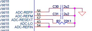
    Here are a couple snaps of the schematic which shows digital and analog grounds connected together as well as the ADC-LO pin connected to ground.  Incidentally there is no way to configure any other pin as analog ground.


    Please make sure you are following the ADC calibration requirements outlined in section 1.8 of the ADC reference guide:

    http://www.ti.com/general/docs/lit/getliterature.tsp?literatureNumber=spru812a&fileType=pdf

    If you are not already doing so, the adc_soc example code in ControlSuite is a great place to begin.

  • Joe,

    Thanks a bunch for drafting your response!

    I have been using the  'Example_2833xAdcSoc.pjt' file in the example file, which I believe calibrates the ADC using the method in section the ADC manual. I've actually tried using every one of the example files associated with the ADC, but all give the same (erroneous) data. 

    As you mentioned, the control card's sheet shows ADCLO connected to analog ground. As mentioned in Section 9 of the ADC calibration document, however, ADCLO is not connected in the actual chip, by default, to ground (http://www.ti.com/lit/an/spraad8a/spraad8a.pdf, page 18). So, I thought that because the ADC is not properly calibrating itself (ie: running the example files consistently gives bad results for data points numbering in the thousands), I assumed that the ADCLO pin was not connected properly in the board . docking station. This is based on my assumption that a faulty ground must be at fault, but do you know of any other problem which could cause different ADC input pins, both plugged into analog ground, to show statistically different results for every example provided? I'd be happy to try almost anything, to get some decent data!

    Thanks in advance for any help or information!

    Best,

    Patrick

  • Patrick- I believe I have reproduced your issue and I'm working toward a solution.  I'll let you know when I figure it out.

  • Patrick- looks like there is a bug in the adc_soc code.  HSPCLK is not getting divided down properly so the ADC is running too fast.  Please see the following thread for the details to fix the code:

    http://e2e.ti.com/support/microcontrollers/tms320c2000_32-bit_real-time_mcus/f/171/t/160912.aspx#596971

    Let me know if this solves your problem.  BTW I have filed a bug to update the example code.