Other Parts Discussed in Thread: TPD8F003, CONTROLSUITE, TPS3828
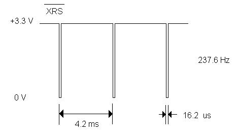
I posted previously in the thread F28335 Unable to Program and XRS Periodically Asserting Low. I'm having problems still though.
Our 1st custom board in the above thread was still having some issues with power, to the point that the success in programming started dropping to 0%. I also noticed that the chip didn't appear to run on its own without the debugger, though I was going to try moving the watchdog disable a bit closer to the start to see if that was the issue. I was never able to reprogram it though.
So we made a fresh copy of our custom board with all the fixes from our trial with board #1. I powered it up and connected the XDS100v3 to it from CCS v5.4. I ran the "Test Connection" in the ccxml file and the JTAG scan paths for DR and IR succeeded with no errors.
But, when I entered debug, I get the error:
C28xx: Error connecting to the target: (Error -1135 @ 0x0) The emulator reported an error. Confirm emulator configuration and connections, reset the emulator, and retry the operation. (Emulation package 5.1.73.0)
I've noticed in other threads this is often accompanied by another error, but this is the one I get every single time. I've run the "Test Connection" a few more times at different rates (10 kHz, 100 kHz, 1 MHz) and they always check out but I still get Error -1135.
I have the JTAG wired generally as specified in the F28335 manual:

The difference is I have a compact TI 20-pin on the XDS100v3, so in addition I also have:
| 15 | SRST - connected to input MR' pin of the power supervisor TPS3828-33, whose output RESET' goes to the F28335 pin XRS' |
| 16 | ground |
| 17 | no connection |
| 18 | No connection |
| 19 | no connection |
| 20 | ground |
In the path between the JTAG port and the F28335, I also have Littelfuse LC03-3.3 transient protectors (EFT and surge rated) and the EMI filter TPD8F003DQDR. I've used the TPD8F003 successfully in JTAG on a Stellaris project before, but the LC03-3.3 is new to this design, I might try removing them next.
Any ideas what the issue is?
For reference, here is my JTAG scan test results:
[Start]
Execute the command:
%ccs_base%/common/uscif/dbgjtag -f %boarddatafile% -rv -o -F inform,logfile=yes -S pathlength -S integrity
[Result]
-----[Print the board config pathname(s)]------------------------------------
C:\DOCUME~1\USER\LOCALS~1\APPLIC~1\.TI\1989394224\
0\0\BrdDat\testBoard.dat
-----[Print the reset-command software log-file]-----------------------------
This utility has selected a 100- or 510-class product.
This utility will load the adapter 'jioserdesusbv3.dll'.
The library build date was 'Apr 1 2013'.
The library build time was '23:55:08'.
The library package version is '5.1.73.0'.
The library component version is '35.34.40.0'.
The controller does not use a programmable FPGA.
The controller has a version number of '4' (0x00000004).
The controller has an insertion length of '0' (0x00000000).
This utility will attempt to reset the controller.
This utility has successfully reset the controller.
-----[Print the reset-command hardware log-file]-----------------------------
The scan-path will be reset by toggling the JTAG TRST signal.
The controller is the FTDI FT2232 with USB interface.
The link from controller to target is direct (without cable).
The software is configured for FTDI FT2232 features.
The controller cannot monitor the value on the EMU[0] pin.
The controller cannot monitor the value on the EMU[1] pin.
The controller cannot control the timing on output pins.
The controller cannot control the timing on input pins.
The scan-path link-delay has been set to exactly '0' (0x0000).
-----[The log-file for the JTAG TCLK output generated from the PLL]----------
Test Size Coord MHz Flag Result Description
~~~~ ~~~~ ~~~~~~~ ~~~~~~~~ ~~~~ ~~~~~~~~~~~ ~~~~~~~~~~~~~~~~~~~
1 512 - 01 00 500.0kHz O good value measure path length
2 512 + 00 00 1.000MHz [O] good value apply explicit tclk
There is no hardware for measuring the JTAG TCLK frequency.
In the scan-path tests:
The test length was 16384 bits.
The JTAG IR length was 3 bits.
The JTAG DR length was 1 bits.
The IR/DR scan-path tests used 2 frequencies.
The IR/DR scan-path tests used 500.0kHz as the initial frequency.
The IR/DR scan-path tests used 1.000MHz as the highest frequency.
The IR/DR scan-path tests used 1.000MHz as the final frequency.
-----[Measure the source and frequency of the final JTAG TCLKR input]--------
There is no hardware for measuring the JTAG TCLK frequency.
-----[Perform the standard path-length test on the JTAG IR and DR]-----------
This path-length test uses blocks of 512 32-bit words.
The test for the JTAG IR instruction path-length succeeded.
The JTAG IR instruction path-length is 3 bits.
The test for the JTAG DR bypass path-length succeeded.
The JTAG DR bypass path-length is 1 bits.
-----[Perform the Integrity scan-test on the JTAG IR]------------------------
This test will use blocks of 512 32-bit words.
This test will be applied just once.
Do a test using 0xFFFFFFFF.
Scan tests: 1, skipped: 0, failed: 0
Do a test using 0x00000000.
Scan tests: 2, skipped: 0, failed: 0
Do a test using 0xFE03E0E2.
Scan tests: 3, skipped: 0, failed: 0
Do a test using 0x01FC1F1D.
Scan tests: 4, skipped: 0, failed: 0
Do a test using 0x5533CCAA.
Scan tests: 5, skipped: 0, failed: 0
Do a test using 0xAACC3355.
Scan tests: 6, skipped: 0, failed: 0
All of the values were scanned correctly.
The JTAG IR Integrity scan-test has succeeded.
-----[Perform the Integrity scan-test on the JTAG DR]------------------------
This test will use blocks of 512 32-bit words.
This test will be applied just once.
Do a test using 0xFFFFFFFF.
Scan tests: 1, skipped: 0, failed: 0
Do a test using 0x00000000.
Scan tests: 2, skipped: 0, failed: 0
Do a test using 0xFE03E0E2.
Scan tests: 3, skipped: 0, failed: 0
Do a test using 0x01FC1F1D.
Scan tests: 4, skipped: 0, failed: 0
Do a test using 0x5533CCAA.
Scan tests: 5, skipped: 0, failed: 0
Do a test using 0xAACC3355.
Scan tests: 6, skipped: 0, failed: 0
All of the values were scanned correctly.
The JTAG DR Integrity scan-test has succeeded.
[End]