Hi everyone, I'm a beginer and i like to know if is absolutely necessary an external oscilloscope to display waveforms of PWMs, i am working with an TMS320c2000 Microcontroller F28027, thanks in advance.
This thread has been locked.
If you have a related question, please click the "Ask a related question" button in the top right corner. The newly created question will be automatically linked to this question.
Hi everyone, I'm a beginer and i like to know if is absolutely necessary an external oscilloscope to display waveforms of PWMs, i am working with an TMS320c2000 Microcontroller F28027, thanks in advance.
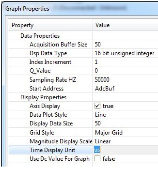
The graph tool can plot data from memory. It cannot plot signal generated by PWM peripheral.
Regards,
Maciej
Hi,
Can't you feedback your PWM outputs to you CAPture inputs? This way you're able to measure your PWM pulse width and, if triggered by PWM interrupts, you'll be able to do some interrupt based logging by add the captured results to an array creating your history. Than you're able to watch the array in your watch window or just export the array to your excel workspace (select al, CTRL+C, Paste in excel) and generate a Graph here.
You're not able to capture your HiRes resolution, but at least your SYSCLK resolution (10ns@100MHz).
Best regards,
Tjarco
Tjarco Boerkoel said:Captured results to an array - creating a history. Then - export the array to Excel
Applaud Tjarco for this post - Excel (& similar) are so powerful - so often identify problems - lead to better (& faster) solutions.
Tjarco's suggestion of feeding back key outputs - to CAPture inputs - inspired!
While always best/safest to monitor the actual, "real-world" conditions (as suggested above) you may also consider regularly "logging" your key PWM variable - over the time/range of interest. (but do this after you've confirmed that the variable selected very well reflects actual PWM duty (or other item of interest))
Here's "proof" - Tjarco's idea - harvested via transfer - ARM's SRAM to Excel: (BLDC motor - 2300RPM Target - under load)
Scale: Hor mS, Vert. RPM (top), PWM variable (bottom) Data (2 of 12 different - 32 bit values) captured @ 1mS intervals
Hi Guys, i really apreciate your help, and i would like to know the following question, if i'll conect pin 3 (ADC-A0) with pin17(EPWM-1A-GPIO00) by a cable conector(wire), i can show the AdcBuf, and that will be the signal of my PWM indeed?, am i right?, thanks in advance..
"I use the microcontroller TMS320F28027"
Sorry - but as I'm here...
PWM may not be properly monitored via "direct connect" to an ADC. Recall PWM is a sequence of width modulated - full-scale swing (i.e. 0 -> 3V3) pulses. And "usually" in the frequency range "above human hearing" for many applications. (although 100Hz or so should work for simpler applications - but "filtering" of such low frequencies will prove a challenge. {i.e. l o n g time constants}
What may work is the creation of an external R-C network (and the R-C's output then fed to the ADC) - which will yield a DC Voltage directly reflective of the PWM's duty cycle. R-C values depend upon the PWM frequency and the response rate you desire. (cb1 departs - ARM land...)
Mileva,
I recommend oscilloscope. You do not need expensive digital one. You can buy inexpensive old, used oscilloscope on any popular auction website.
As long as the device is operational you will not regret the purchase.
Regards,
Maciej
MaciejKucia said:I recommend oscilloscope
As do most - here.
Should cost be an issue - and you still seek "modern" performance - consider a PC-based version w/best "data capture" specs w/in your budget...
Hi Mileva!
There are a reasonable low-cost and convenient hybrid solutions with the USB interface and the display on the PC monitor like this (and with a spectrum analyzer function also)
http://www.velleman.co.uk/contents/en-uk/p382_pcsu1000.html
Regards,
Igor
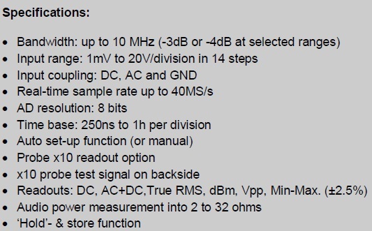
Hi Guys, an electronic shop near my house is selling the follow oscilloscope HPS140i with the following characteristics :
Here you are the link: http://www.hps140.com/
The question is:
My exercises consist of generating signals PWMs of 10KZ, 50KHz and a signal PWM with period of 500 miliseconds.
¿Can I show the PWMs signals of the PICCOLO with the Oscilloscope HPS140i, if it working at 10MHz?, taking into account the piccolo works up 60 MHz, but i think the PWMs signals of the PICCOLO are signal bellow 10MHz. ¿am i right?..
For example show the waveforms of ePWM1 and ePWM2 signals will be imposible to show with hps140i oscilloscope. ¿am i right?
Hi Mileva!
Mileva K. said:My exercises consist of generating signals PWMs of 10KZ, 50KHz and a signal PWM with period of 500 miliseconds.
1 Objectively. This is a acceptable option for your current task.
2 Subjectively. AD resolution 8 bit is not enough (better 12).
3 Rerspectively. 10 MHz is not enough (better 50-100). But now it is difficult to determine your future needs.
You need to decide himself. Based on your financial possibilities.
Regards,
Good luck,
Igor
It is a very hard job to fully & properly anticipate both your present and future needs.
And - as past US Defense Secty. stated, "you encounter known (unknowns) and unknown (unknowns.)"
Unless you can "steal" that scope - believe you will be far better served by choosing a PC/Hybrid Scope package. The "front-end" of PC/Hybrid will vastly exceed that of the local shop's offering - and the front-end is an especially crucial part of any scope capability. (proven by Tek/Agilent emphasis)
Most here will guarantee that your needs will expand - beyond your "current" yellow highlights - and the PC/Hybrid solution best promises to meet your present and future requirements...