This thread has been locked.

If you have a related question, please click the "Ask a related question" button in the top right corner. The newly created question will be automatically linked to this question.

Error connecting to f28335 experimenters kit

Other Parts Discussed in Thread: UNIFLASH, TPS62400

Hi 

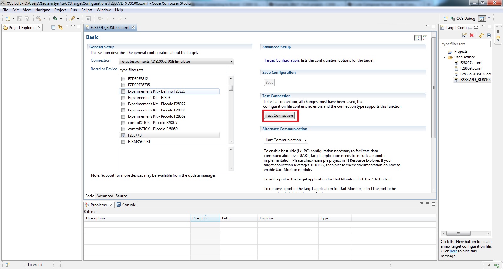
I am current working with Delfino experimenters kit. It was working until yesterday and from today, I get the following message whenever I try to connect with CCSV4

"Error connecting to the target:

(Error -1041 @ 0x0)
The emulator reported an error. Confirm emulator configuration and connections, reset the emulator, and retry the operation.
(Release 5.0.429.0)"

I restarted CCSV and the kit. But none of these worked.  Has anyone faced this error??

  • Hi Vivek,

    What does "Test Connection" in Target configuration say? Secondly, do try with CCS Uniflash application too. Finally if both don't work, try upgrading your CCS to the latest version ie V5.5

    Let me know what your observations are.

    Regards,

    Gautam

  • HI Gautam

    This is the screenshot of CCSV4. I could not find the 'test connection'. Am I missing something or is this option only available in CCSV5? Secondly I have not used CCS uniflash application. I will try it and will update the results soon.

  • Hi Gautam

    While using CCS Uniflash to 'calculate check sum', 'unlock', 'starting frequency test' etc, I got the following error when 

    [15:02:28] FATAL >> C28xx: Error connecting to the target: (Error -1015 @ 0x0) Device is not responding to the request.  Device may be locked, or the emulator connection may be unreliable. Unlock the device if possible (e.g. use wait in reset mode, and power-cycle the board). If error persists, confirm configuration and/or try more reliable JTAG settings (e.g. lower TCLK). (Emulation package 5.1.232.0) '

    I also update my CCSV4, but go the same error message as in my first post.

    regards

  • You'll find "Test connection" in CCS v5 which will perform JTAG integration test. It will look like:

    Regards,

    Gautam

  • Hi Gautam

    I get the following message while doing test configuration using CCSV5

    "

    [Start]

    Execute the command:

    %ccs_base%/common/uscif/dbgjtag -f %boarddatafile% -rv -o -F inform,logfile=yes -S pathlength -S integrity

    [Result]


    -----[Print the board config pathname(s)]------------------------------------

    C:\Users\dipti\AppData\Local\.TI\693494126\
    0\0\BrdDat\testBoard.dat

    -----[Print the reset-command software log-file]-----------------------------

    This utility has selected a 100- or 510-class product.
    This utility will load the adapter 'jioserdesusb.dll'.
    The library build date was 'Aug 20 2013'.
    The library build time was '22:56:19'.
    The library package version is '5.1.232.0'.
    The library component version is '35.34.40.0'.
    The controller does not use a programmable FPGA.
    The controller has a version number of '4' (0x00000004).
    The controller has an insertion length of '0' (0x00000000).
    This utility will attempt to reset the controller.
    This utility has successfully reset the controller.

    -----[Print the reset-command hardware log-file]-----------------------------

    The scan-path will be reset by toggling the JTAG TRST signal.
    The controller is the FTDI FT2232 with USB interface.
    The link from controller to target is direct (without cable).
    The software is configured for FTDI FT2232 features.
    The controller cannot monitor the value on the EMU[0] pin.
    The controller cannot monitor the value on the EMU[1] pin.
    The controller cannot control the timing on output pins.
    The controller cannot control the timing on input pins.
    The scan-path link-delay has been set to exactly '0' (0x0000).

    -----[The log-file for the JTAG TCLK output generated from the PLL]----------

    There is no hardware for programming the JTAG TCLK frequency.

    -----[Measure the source and frequency of the final JTAG TCLKR input]--------

    There is no hardware for measuring the JTAG TCLK frequency.

    -----[Perform the standard path-length test on the JTAG IR and DR]-----------

    This path-length test uses blocks of 512 32-bit words.

    The test for the JTAG IR instruction path-length failed.
    The JTAG IR instruction scan-path is stuck-at-zero.

    The test for the JTAG DR bypass path-length failed.
    The JTAG DR bypass scan-path is stuck-at-zero.

    -----[Perform the Integrity scan-test on the JTAG IR]------------------------

    This test will use blocks of 512 32-bit words.
    This test will be applied just once.

    Do a test using 0xFFFFFFFF.
    Test 1 Word 0: scanned out 0xFFFFFFFF and scanned in 0x00000000.
    Test 1 Word 1: scanned out 0xFFFFFFFF and scanned in 0x00000000.
    Test 1 Word 2: scanned out 0xFFFFFFFF and scanned in 0x00000000.
    Test 1 Word 3: scanned out 0xFFFFFFFF and scanned in 0x00000000.
    Test 1 Word 4: scanned out 0xFFFFFFFF and scanned in 0x00000000.
    Test 1 Word 5: scanned out 0xFFFFFFFF and scanned in 0x00000000.
    Test 1 Word 6: scanned out 0xFFFFFFFF and scanned in 0x00000000.
    Test 1 Word 7: scanned out 0xFFFFFFFF and scanned in 0x00000000.
    The details of the first 8 errors have been provided.
    The utility will now report only the count of failed tests.
    Scan tests: 1, skipped: 0, failed: 1
    Do a test using 0x00000000.
    Scan tests: 2, skipped: 0, failed: 1
    Do a test using 0xFE03E0E2.
    Scan tests: 3, skipped: 0, failed: 2
    Do a test using 0x01FC1F1D.
    Scan tests: 4, skipped: 0, failed: 3
    Do a test using 0x5533CCAA.
    Scan tests: 5, skipped: 0, failed: 4
    Do a test using 0xAACC3355.
    Scan tests: 6, skipped: 0, failed: 5
    Some of the values were corrupted - 83.3 percent.

    The JTAG IR Integrity scan-test has failed.

    -----[Perform the Integrity scan-test on the JTAG DR]------------------------

    This test will use blocks of 512 32-bit words.
    This test will be applied just once.

    Do a test using 0xFFFFFFFF.
    Test 1 Word 0: scanned out 0xFFFFFFFF and scanned in 0x00000000.
    Test 1 Word 1: scanned out 0xFFFFFFFF and scanned in 0x00000000.
    Test 1 Word 2: scanned out 0xFFFFFFFF and scanned in 0x00000000.
    Test 1 Word 3: scanned out 0xFFFFFFFF and scanned in 0x00000000.
    Test 1 Word 4: scanned out 0xFFFFFFFF and scanned in 0x00000000.
    Test 1 Word 5: scanned out 0xFFFFFFFF and scanned in 0x00000000.
    Test 1 Word 6: scanned out 0xFFFFFFFF and scanned in 0x00000000.
    Test 1 Word 7: scanned out 0xFFFFFFFF and scanned in 0x00000000.
    The details of the first 8 errors have been provided.
    The utility will now report only the count of failed tests.
    Scan tests: 1, skipped: 0, failed: 1
    Do a test using 0x00000000.
    Scan tests: 2, skipped: 0, failed: 1
    Do a test using 0xFE03E0E2.
    Scan tests: 3, skipped: 0, failed: 2
    Do a test using 0x01FC1F1D.
    Scan tests: 4, skipped: 0, failed: 3
    Do a test using 0x5533CCAA.
    Scan tests: 5, skipped: 0, failed: 4
    Do a test using 0xAACC3355.
    Scan tests: 6, skipped: 0, failed: 5
    Some of the values were corrupted - 83.3 percent.

    The JTAG DR Integrity scan-test has failed.

    [End]"

  • I hope you're using XDS100v2 as your emulator in Target Configuration and not any other. Also, check the control card's switch SW1 placement; it should be in UP/ON position.

    Regards,

    Gautam

  • Hi Gautam

    Thank you for the response. I was selecting XDS100V1 until now, but after you had recommended - I tried XDS100V2 but the error looks the same.

    "

    [Start]

    Execute the command:

    %ccs_base%/common/uscif/dbgjtag -f %boarddatafile% -rv -o -F inform,logfile=yes -S pathlength -S integrity

    [Result]


    -----[Print the board config pathname(s)]------------------------------------

    C:\Users\dipti\AppData\Local\.TI\693494126\
    0\0\BrdDat\testBoard.dat

    -----[Print the reset-command software log-file]-----------------------------

    This utility has selected a 100- or 510-class product.
    This utility will load the adapter 'jioserdesusb.dll'.
    The library build date was 'Aug 20 2013'.
    The library build time was '22:56:19'.
    The library package version is '5.1.232.0'.
    The library component version is '35.34.40.0'.
    The controller does not use a programmable FPGA.
    The controller has a version number of '4' (0x00000004).
    The controller has an insertion length of '0' (0x00000000).
    This utility will attempt to reset the controller.
    This utility has successfully reset the controller.

    -----[Print the reset-command hardware log-file]-----------------------------

    The scan-path will be reset by toggling the JTAG TRST signal.
    The controller is the FTDI FT2232 with USB interface.
    The link from controller to target is direct (without cable).
    The software is configured for FTDI FT2232 features.
    The controller cannot monitor the value on the EMU[0] pin.
    The controller cannot monitor the value on the EMU[1] pin.
    The controller cannot control the timing on output pins.
    The controller cannot control the timing on input pins.
    The scan-path link-delay has been set to exactly '0' (0x0000).

    -----[The log-file for the JTAG TCLK output generated from the PLL]----------

    There is no hardware for programming the JTAG TCLK frequency.

    -----[Measure the source and frequency of the final JTAG TCLKR input]--------

    There is no hardware for measuring the JTAG TCLK frequency.

    -----[Perform the standard path-length test on the JTAG IR and DR]-----------

    This path-length test uses blocks of 512 32-bit words.

    The test for the JTAG IR instruction path-length failed.
    The JTAG IR instruction scan-path is stuck-at-zero.

    The test for the JTAG DR bypass path-length failed.
    The JTAG DR bypass scan-path is stuck-at-zero.

    -----[Perform the Integrity scan-test on the JTAG IR]------------------------

    This test will use blocks of 512 32-bit words.
    This test will be applied just once.

    Do a test using 0xFFFFFFFF.
    Test 1 Word 0: scanned out 0xFFFFFFFF and scanned in 0x00000000.
    Test 1 Word 1: scanned out 0xFFFFFFFF and scanned in 0x00000000.
    Test 1 Word 2: scanned out 0xFFFFFFFF and scanned in 0x00000000.
    Test 1 Word 3: scanned out 0xFFFFFFFF and scanned in 0x00000000.
    Test 1 Word 4: scanned out 0xFFFFFFFF and scanned in 0x00000000.
    Test 1 Word 5: scanned out 0xFFFFFFFF and scanned in 0x00000000.
    Test 1 Word 6: scanned out 0xFFFFFFFF and scanned in 0x00000000.
    Test 1 Word 7: scanned out 0xFFFFFFFF and scanned in 0x00000000.
    The details of the first 8 errors have been provided.
    The utility will now report only the count of failed tests.
    Scan tests: 1, skipped: 0, failed: 1
    Do a test using 0x00000000.
    Scan tests: 2, skipped: 0, failed: 1
    Do a test using 0xFE03E0E2.
    Scan tests: 3, skipped: 0, failed: 2
    Do a test using 0x01FC1F1D.
    Scan tests: 4, skipped: 0, failed: 3
    Do a test using 0x5533CCAA.
    Scan tests: 5, skipped: 0, failed: 4
    Do a test using 0xAACC3355.
    Scan tests: 6, skipped: 0, failed: 5
    Some of the values were corrupted - 83.3 percent.

    The JTAG IR Integrity scan-test has failed.

    -----[Perform the Integrity scan-test on the JTAG DR]------------------------

    This test will use blocks of 512 32-bit words.
    This test will be applied just once.

    Do a test using 0xFFFFFFFF.
    Test 1 Word 0: scanned out 0xFFFFFFFF and scanned in 0x00000000.
    Test 1 Word 1: scanned out 0xFFFFFFFF and scanned in 0x00000000.
    Test 1 Word 2: scanned out 0xFFFFFFFF and scanned in 0x00000000.
    Test 1 Word 3: scanned out 0xFFFFFFFF and scanned in 0x00000000.
    Test 1 Word 4: scanned out 0xFFFFFFFF and scanned in 0x00000000.
    Test 1 Word 5: scanned out 0xFFFFFFFF and scanned in 0x00000000.
    Test 1 Word 6: scanned out 0xFFFFFFFF and scanned in 0x00000000.
    Test 1 Word 7: scanned out 0xFFFFFFFF and scanned in 0x00000000.
    The details of the first 8 errors have been provided.
    The utility will now report only the count of failed tests.
    Scan tests: 1, skipped: 0, failed: 1
    Do a test using 0x00000000.
    Scan tests: 2, skipped: 0, failed: 1
    Do a test using 0xFE03E0E2.
    Scan tests: 3, skipped: 0, failed: 2
    Do a test using 0x01FC1F1D.
    Scan tests: 4, skipped: 0, failed: 3
    Do a test using 0x5533CCAA.
    Scan tests: 5, skipped: 0, failed: 4
    Do a test using 0xAACC3355.
    Scan tests: 6, skipped: 0, failed: 5
    Some of the values were corrupted - 83.3 percent.

    The JTAG DR Integrity scan-test has failed.

    [End]

    "

    And regarding turning the board-on, diode LD1 is green and the computer is reading the board. So, I think the board is turned on, is not it?

    Do you think there could be some problem with the docking station?

    regards

  • And regarding turning the board-on, diode LD1 is green and the computer is reading the board. So, I think the board is turned on, is not it?

    I was talking about the SW1 on the control card and not the docking station :)

    Regards,

    Gautam

  • Hi Gautam

    Oh my bad! I was just used to using SW1 in docking station. Anyways,  SW1 in the control card is also 'on'. 

    regards

  • Vivek, check these out:

    1. For any overheats on the controlCard esp. the controller U1 and switching regulator U2.

    2. If the above seem fine, check the voltages on controlCard and compare them with that in schematics.

    3. Uninstall XDS100 drivers, restart and reinstall them. Check with test connection.

    4. Also, there is a possibility that the device has been permanently locked.

    Regards,

    Gautam

  • Hi Gautam

    Thanks..I will try it tomorrow and update this thread.

    regards

  • Sure sure. Take your time but don't forget to update.

    Regards,

    Gautam

  • Hi Gautam

    1. U1 and U2 are appreciably hot after turning the board on for 7-10 minutes.I did not have an IR thermometer but could not keep my finger in U2 for more than 5 secs and in U1 for more than 10secs - funny back of the envelope kind of correlation :)
    2. Many of the ICs like U3, U4, U5, U6, DN1, DN2, DN3 (of card) ,  pin v3.3 of Jumper J3(docking station)does not have a 3v3 supply as mentioned in the schematic instead the voltage is around 0.6V. But U2 (of card) is supplied by nearly 5V and U2 of the docking station is generating 3v3. And, all the other jumpers in the docking station marked with respective voltage (5 or 3.3V) has the corresponding voltage
    3. 'Uninstall XDS100 drivers' I had not installed XDS drives from the link that you had provided. I have 'Windows driver package - EWA technologies, Inc. (XDS560) TI_emulators. Probably this was installed while installing uniflash or CCSV5.

    I can see that there is definitely some problem with 3.3V supply? What do you say Gautam? Should I investigate things further?

  • Hi Vivek,

    There's the culprit :)

    I can see that there is definitely some problem with 3.3V supply? What do you say Gautam? Should I investigate things further?

    Yup, I guess your regulator might've been damaged. Once the same happened to me too; replacing U2 did the trick. But till date I was not able to find out the reason why it failed; so I blame the "ESD"!

    Regards,

    Gautam

  • Hi gautam

    Do you mean that you replaced the U2 of control card to solve this problem?? And, one quick thing regulator of docking station is working. Is there another regulator for card?

    Regards

  • Do you mean that you replaced the U2 of control card to solve this problem??

    Replacing U2 on controlCard did solve my problem. In your case U2 seems to be damaged but don't know about the health of other components. After replacing U2 you'll be able to determine other's health.

    Is there another regulator for card?

    U2 is the IC that works as a regulator for the MCU : TPS62400, its a step-down converter.

    Regards,

    Gautam

  • Hi Gautam

    Just wanted to update. I could not replace U2 :( So I went for buying a new card. The new card works :)

    regards

  • Vivek, that's a great news. Yes replacing U2 can be painful :)

    Do close this thread by verifying the answer.

    Regards,

    Gautam