This thread has been locked.

If you have a related question, please click the "Ask a related question" button in the top right corner. The newly created question will be automatically linked to this question.

No source available for "0x3ff5f5" (F28027F)

Other Parts Discussed in Thread: DRV8301, CONTROLSUITE, MOTORWARE

Hi All,

I'm working on a custom speed controller and am having trouble loading a program to the MCU --TMS320F28027FPTT...

I was initially having no trouble with this but I accidentally smoked the MCU by shorting something with my scope probe while troubleshooting something else. I have since replaced the MCU and the DRV8301 (just to be safe) and now I get the title error.

This is what it looks like:

with flash program setting: Program, Verify..

and with flash program setting: Erase, Program, Verify

slightly different...

If I enable silicon real-time mode, most of the registers go to 0x0BAD or Error: unable to read...ie

Other info:

After initial failure to load, I can hit run->reset->rest cpu and the play button will come up (it doesn't when I just hit debug) which I can press and see the CPUTimer and GPIO registers updating.... (The MCU is clearly not running my code though)...

The code I am running is not the issue...I used it successfully before I first blew up the MCU and I have used it on launchpads.

 JTAG Test Connection result:

'The JTAG DR Integrity scan-test has succeeded.'

I have methodically checked all pertinent connections:

MCU power (3v3 from DRV8301 buck)/

MCU Grounds/

Jtag Header connections are all solid (checked a dozen times).

I am confident the MCU has not been stressed (no high voltage, static or high temperatures) but, the nature of the board means that it is possible that there may have been something conductive between traces or something like that... Do I have a dead MCU or could it be something else?

**Not my JTAG emulator either, I initially thought this and have replaced it which made no difference at all.

Thanks for any advice ob this...

**********************************************************************************************************************

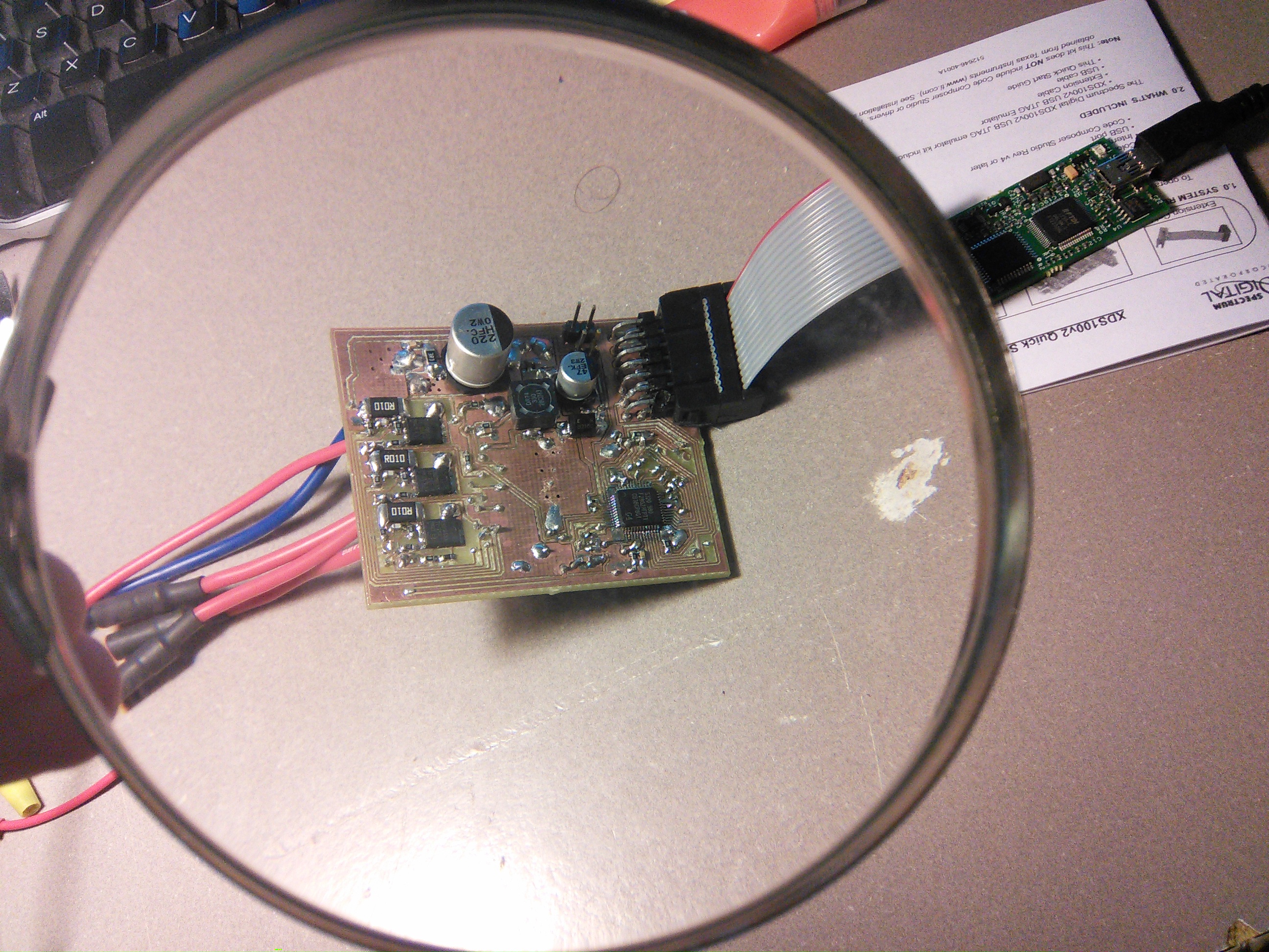
What I meant by 'nature of the board':

  • Hi,

    You don't have to worry about the "No source available" error.

    Here's more info on that: http://e2e.ti.com/support/microcontrollers/c2000/f/171/t/252845.aspx

    Also, the board layout seems very very... (can't describe in words). If your MCU was dead, you would not be able to program it. There can be certain peripheral failures though!

    Regards,

    Gautam

  • Thanks Gautam,

    Gautam Iyer said:
    Also, the board layout seems very very... (can't describe in words). If your MCU was dead, you would not be able to program it.

    I'd be interested to here your adjective at the end of 'very very'??? It's the very first prototype and my first go at board layout so I would be interested in any tips....

    If its got nothing to do with 'No source available', why can't I run the program? Do you have any trouble shooting tips?

    perhaps I wasn't very clear, ill try to be more succinct - my steps:

    *Check JTAG connection...

    *JTAG test succeeds so I go ahead and press debug...

    *Everything seems fine but the green play button is greyed out and the aforementioned error appears..

    *By hitting CPU reset, I can get the green play button to become 'pressable' but when I press it, it either comes straight back out of play or I just can't manipulate any registers. e.g. if I try to toggle GPIO12 by changing GPATOGGLE to 0x1000, GPIODAT does not change. However, if it gets to this point, I can see CPUtimers changing and some other registers that are set by default at reset....

  • Thanks for the detailed description, Patrick. I would first like you to check with one of the simple example code from controlSuite. Let me know whether that works or not!

    Regards,

    Gautam

  • Gautam, 

    -My first thought too- no none of the examples directly from CS work - exactly the same problem... And, motorware examples give a different error - as follows (Unchanged instaspin lab 3A - my HW is setup to be compatible with DRV8301BOOST code directly). I suspect because these try to load onto flash? only difference I could think of.

    I should also stress that this board was working with instaspin projects.... Well, not really, I was trouble shooting a lack of PWM from the MCU when I shorted something, but, I had correct DC bus feedback and I was running instaspin labs on this board without any trouble....

    After I destroyed the MCU, I replaced it and the DRV8301 and am fairly certain that my hardware is in the same condition as it was before I broke the MCU the first time...

    Thanks

  • Then, there's/are some other components that is/are hampering the working of the board! So running from RAM and flash both don't work, right? Check out the voltage levels on the board (seems challenging), also check for any overheating components.

    Regards,

    Gautam 

  • Gautam, thanks...

    I'm an idiot... The problem is a lack of voltage, the buck is only putting out 2.54V, which will be starving the MCU and causing these problems....

    I swear I did check this, but it was while the MCU was not on the board and then I didn't want to bridge something so I didn't check the live voltage again....

    I don't know if you have much experience with the DRV8301, but my feedback to the buck is at 0.66V instead of 0.8V... I'm troubleshooting it now, but since I know the resistor values are correct, and that it was outputting 3.3V before I mounted the MCU, I am not sure whats going on??? Maybe a high impedance bridge? Would that cause the feedback to be low?

    - I also thought that maybe the power pad could be floating, but I don't think so as that would cause a much higher buck voltage, not lower... (Say if DRV8301 gnd was floating at 1/2V or something?) - I was careful to make sure there was a solid power pad to ground connection.

    Anyway at least I now know what I am chasing - so thank you for that.... Any tips on this issue appreciated as always.

  • That's great you were able to track the issue.

    I don't know if you have much experience with the DRV8301, but my feedback to the buck is at 0.66V instead of 0.8V... I'm troubleshooting it now, but since I know the resistor values are correct, and that it was outputting 3.3V before I mounted the MCU, I am not sure whats going on??? Maybe a high impedance bridge? Would that cause the feedback to be low?

    Nope, I don't have experience with DRV8301 so I won't be able to comment on that.

    Do let us know if your issues are resolved.

    Regards,

    Gautam

  • Hey Gautam, 

    Problem solved!

    Turns out the cause was a 'bad' connection on the main DC bus to the DRV8301 PVDD....

    Everything is now working re JTAG.

    THANK YOU again/ 

  • Great Work!

    Goodluck & Regards,

    Gautam