Hi,
I'm rather new to C2000 family, currently trying to get some ADC to work, with best possible sampling rate. What i'm struggling with is adc generating noise-like errors while fed with onboard PWM (I have to add, similar thing was happening when using external sinewave generator as signal input).
I'm using F28069 controlSTICK, CCS v6. program i'm testing is Lab3 from C2000 One Day Workshop : http://processors.wiki.ti.com/index.php/C2000_Piccolo_One-Day_Workshop_Module_3
Program was modified so i could adjust period, and duty cycle of measured pwm.
Basically: ADC is triggered from ePWM, at rate of 50kHz. Additional PWM signal is generated (2kHz) and fed to ADC. I'm changing PWM signal period and duty cycle in watch expression window.
Issue is, ADC generates nice results for some frequencies, and errors for others (error group being bigger).
Here are examples:
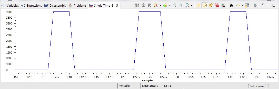
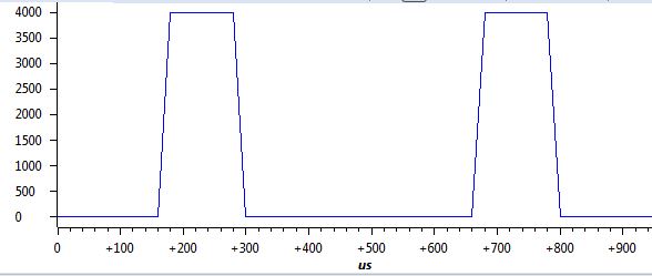
2kHz (default for lab3)
2kHz PWM
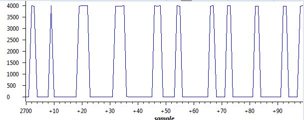
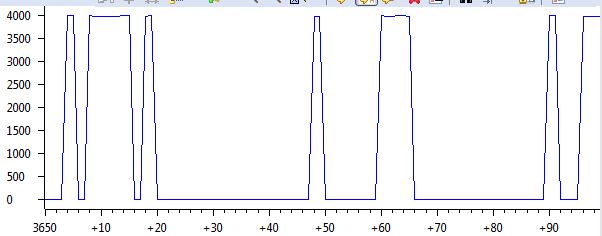
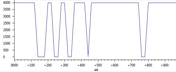
3kHz PWM
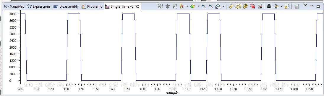
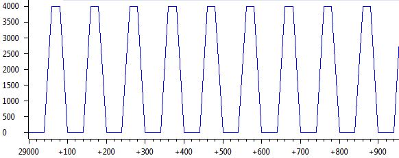
10kHz PWM
3kHz graph looks like samples were corrupted or something. At first i thought, that it's related to start of conversion/end of conversion, but if that was the case, then middle samples should be fine. This noise like corruption happens at some frequencies, while others are totally fine. I have to add, oscilloscope shows that all pwms are totally fine, so issue must be adc-side.
I would greatly aprreciate any feedback on this issue.
Best regards,
Karol