This thread has been locked.

If you have a related question, please click the "Ask a related question" button in the top right corner. The newly created question will be automatically linked to this question.

PMSM FOC current control loop problem

Other Parts Discussed in Thread: CONTROLSUITE, DRV8312

Hello everyone~

I have a DRV8312 kit with F28035 control card, I found the project from C:\ti\controlSUITE\development_kits\DRV8312-C2-KIT_v128\PM_Sensorless

I start to learn the "sensored" FOC control with this project, I have check everything from LEVEL 1 to LEVEL 3 according to the application note, and my problem is in LEVEL 4.

LEVEL 4  is trying to do the current control loop, when I set the lsw=0( Lock rotor, theta=0, Iq_Ref=0, Id_Ref=_IQ(0.2) ) or lsw=1( spin motor,  theta is coming from ramp function(rg1.Out), Iq_Ref=_IQ(0.2), Id_Ref=0 ), I can see the two current PI controller work well in debug watch windows, Id_Fdb keeping track Id_Ref, Iq_Fdb keeping track Iq_Ref. 

In the meanwhile, I also check the qep macro, both qep1.ElecTheta and rg1.Out are of saw-tooth wave shape and have the same period, same direction and do the qep calibration angle for Encoder.

The problem is when I set lsw=2( theta=qep1.ElecTheta, Iq_Ref=_IQ(0.2), Id_Ref=0 ), the motor( no load) will rapidly accelerate to a very high speed, the two current PI controller was saturated, Id_Fdb can not track Id_Ref, Iq_Fdb can not track Iq_Ref.

The block diagram like this

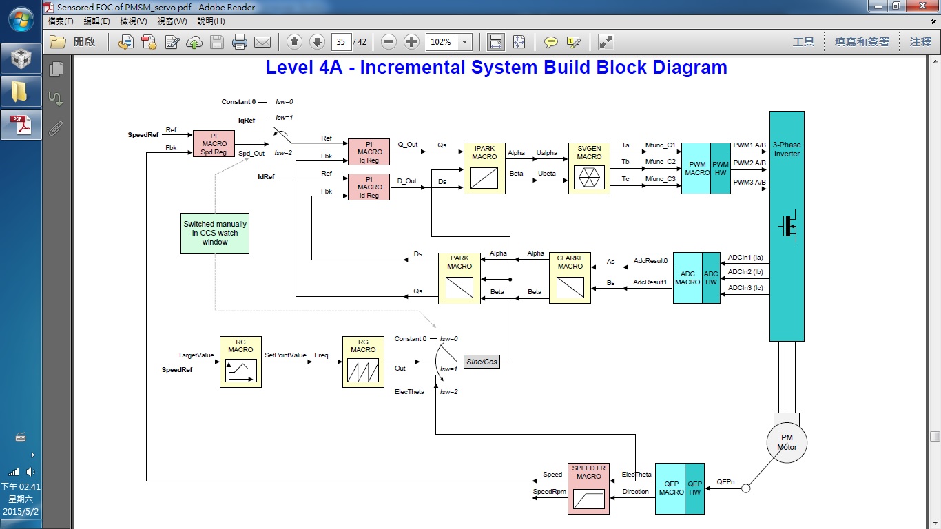
Does anyone have the same problem with me? Or do I have something wrong?

Thank you guys~~

  • Hi Jerry,

    Notice that lsw from 1 to 2 affects who sources the angle information, but also changes whether you use the speed loop or not.

    Lab 4 is the first lab that really tests the speed loop and the PID gains likely need to be edited so that they work with your system/motor/load requirements.
    https://e2e.ti.com/support/microcontrollers/c2000/f/171/p/183220/661798


    Thank you,
    Brett

  • Hi~Thanks for your reply.
    Actually,I just test the current loop,not speed loop. The command is Iq_ref=constant,Id_ref=0.
    The problem is when I change the lsw from “1”to“2”,it means change the electric angle of FOC transformation,from “rg1.out” to “qep.elec_theta”. The phenomenon is the motor spin smoothly according to the “rg1.out”,the Id and Iq PI controller work well in “lsw=1”. The motor start spin quickly in “lsw=2”, and I discover the two PI current controller was saturated. But the interesting thing is when I use my hand to give motor some external load,everything back to the normal situation. Could anyone explain why the motor without load will start to spin rapidly in current mode? Thanks~